
Journey Martinson

Spencer Goodman

Jake WAlejko

Kalina Burns
Achievement House, Inc.
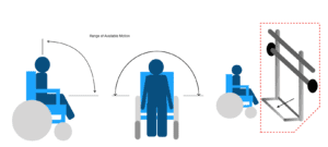
The user should be able to remain seated in their wheelchair while performing the workout.
Resistance Band Rack
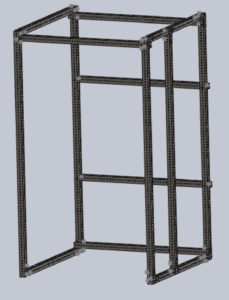
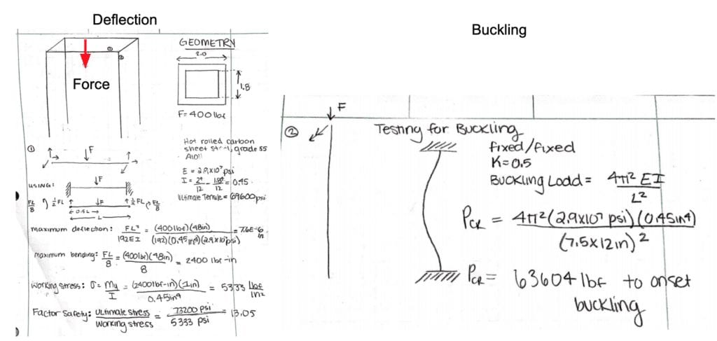
Dimensions: 7.5 ft x 4 ft x 4ft
The resistance band rack is designed to have hooks placed on it wherever the trainer desires. Resistance bands can be attached to these hooks, and a wheelchair user can roll into the structure and complete various exercises.
Punching Bag
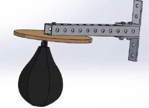
Dimensions: 1.5 ft x 1.0 ft
The punching bag attachment was included for a specific athlete that stressed her interest in boxing to the team. The punching bag can be placed at different heights to allow it to be used by those standing or sitting down.
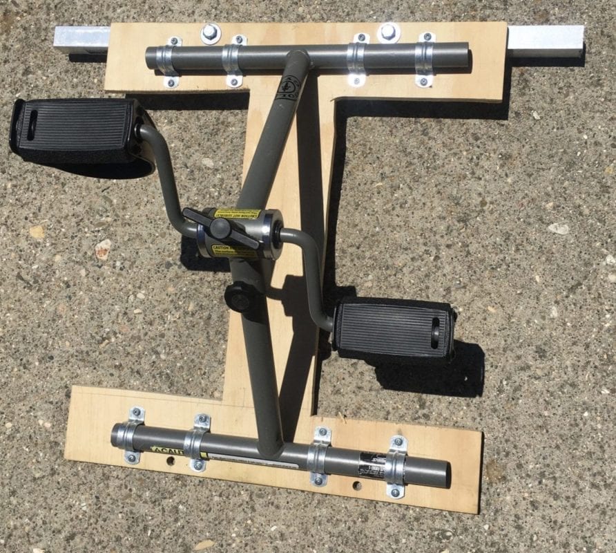
Pedaler Attachment
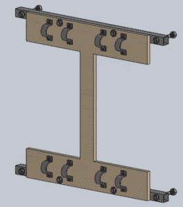
Dimensions: 1.5 ft x 1.5 ft
The pedaler attachment was included to help the athletes achieve a cardiovascular exercise. A portable pedaling device can be attached to the brackets shown above. The attachment can be placed at different heights so that it can be used for pedaling with the arms or with the legs. The resistance of the pedaling motion can be adjusted for the athletes’ varying ranges of strength.
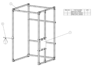
Resistance Band Rack
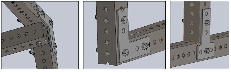
The resistance rack will be assembled together via the three connection methods shown above. The “L” and “T” brackets shown are made of 1/8″ galvanized steel and were donated by Home Depot and Lowes. They are connected to the frame with Grade 5 galvanized steel bolts, which are commonly used in automobile suspension systems.
Punching Bag
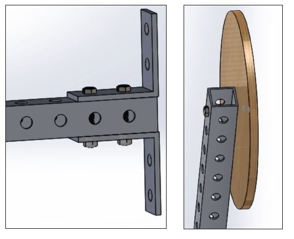
To manufacture the punching bag attachment, bolt the 2 corner L-brackets to the top and bottom face of the 18″ perforated steel beam (shown in the left image). Then, attach the swivel mount and wooden platform to the other end of the steel beam. The speedbag can then be attached to the swivel mount.
Pedaler Attachment
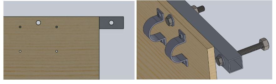
Once the appropriate holes have been drilled according to the pedaler engineering drawings, the aluminum square tubing can be bolted to the wood platform.
The pedaler can then be attached to the wood platform by clamping it with the U-brackets as shown above.