the Team
We are Cal Poly’s ASHRAE Design Competition Team

Scott Ficken
Team Leader/Design Support
I was born and raised in Walnut Creek, California. My hobbies include watching and playing sports, playing video games, and hanging out with friends and family. My plans for after graduation are working for Southland Industries in Union City, California as a Design Engineer.

Leon Saqui
Fan Coil System designer
Hello! I am from Fairfield, California, home of the Jelly Belly jelly bean! Along with being an excellent engineer, I am well versed in the art of music. My primary instrument of choice is the electric bass guitar. I can also play the guitar and piano. Additional hobbies of mine include biking and playing video games. After graduation I will be a Designer at AlfaTech in San Francisco, California.

Dante Saville
variable refrigerant flow designer
Hello! I am from Cave Creek, Arizona, home of excessive sun and heat. In my free time, I tend to explore the outdoors and go hiking and fishing. I also am an avid cook and baker and enjoy the mixture of art and science. My time at Cal-Poly has given me an appreciation and affinity for a variety of fields and subject matters and I will follow where my interest leads.

francisco Martinez
variable air volume designer
I was born and raised in King City, California where I went to high school and eventually went to Cuesta College and from there transferred to Cal Poly. Some of my hobbies include gaming on the Xbox, and spending quality time with family. Once Poly is wrapped up, I will start the next chapter of my life which will include working for Silicone Valley Mechanical in San Jose.
Acknowledgements
We want to give a very special thanks to Dr. Mott, and Dr. Peuker who were fundamental in our HVAC&R concentration at Cal Poly. Dr. Peuker is the director of the HVAC&R Program. Dr. Mott was our senior project advisor and she made this experience very smooth and as easy as it can get. She was flexible with how we managed the work as long as we met each deadline. This taught us that regardless of the roadblocks along the way, deadlines need to be met in a timely manner, and that kind of experience is critical when we graduate and go on to working for companies where deadlines need to be met. On top of that, both Dr. Peuker and Dr. Mott care about their students both in class and outside of it and those are the kinds of professors that you will always remember and that’s something we can all agree on.
Our Project Videos
3 system Designs: vav, vrf, fcu
Problem Statement
The design objectives are to obtain a suitable heating, ventilation, and air conditioning system for the document storage facility located in Mumbai, India, encompassing fragile and sensitive archives and comfortable viewing and working spaces for staff and visitors alike. The building operates from 8:00 to 18:00 six days per week. The building is not open on Sunday. There are no temperature or relative humidity setbacks during unoccupied operation for spaces where materials are stored.
Owner Requirements
Use the latest innovative technologies
and concept to meet ASHRAE Standard 189.1.Have excellent indoor environmental
quality that ensures materials are not damaged.Maximize usable space including
reducing the amount of space needed above ceilings in order to provide maximum
ceiling heights.Have the best life cycle cost for the
applicable climate and the owner’s budget.Design an easily serviceable,
maintainable, and secure facility that has low utility and maintenance costs.Maintain document storage areas to a
temperature of 65°F ± 2°F and a relative humidity maintained at 40% ± 10,
maximum variation for less than one hour.Maintain certain document viewing areas
to a temperature of 70°F ± 2°F with relative humidity maintained at 50% ± 10%
over an hour.Operate building at positive pressure
to prevent unwanted infiltration.Filter all ventilation air filtered to
prevent harmful contaminants from damaging items in the collection.Meet requirements for class 7 clean
spaces in the Archives and Rare Book Collection/Librarian/Reading spaces.The owner’s budget is 350 USD/ft2 (3,767 USD/m2).
Each system will be analyzed using a 50-year life cycle cost, a 7% return on
investment, and a 3% inflation rate. Utility escalation rates are based on a
10-year average historical increase for each resource.
Design concept
- Every system was designed using the sensible load found using Trace 700. Then using the owner requirements set point temperature along with the outside dry bulb temperature, the CFM for each space was calculated.
- Each system handles different load amounts and in different ways. Comparing all three systems was the main directive in order to suggest the best system to the owner by seeing which system met each system requirement in the best manner.
VRF System
how it works
In the variable refrigerant flow terminal unit either liquid or vapor refrigerant flows depending on whether heating (vapor refrigerant) or cooling (liquid refrigerant) is needed. The heating or cooling is achieved by taking advantage of the amount of energy that is either released or extracted from/to the refrigerant delivered to the indoor unit. The refrigerant phase change occurs in the coil that is inside each indoor unit, effectively heating or cooling the air that passes over the coil in the terminal unit. The thermostat for each zone controls whether the coil in the indoor unit is in heating or cooling mode, and the amount of heating/cooling required. In addition to the coil, each indoor unit has a fan that circulates air from the zone and passes it over the coil.
VAV System
how it works
The variable air volume (VAV) terminal unit distributes air from the air handling unit to the proper diffusors within the zone that the VAV terminal unit controls for room conditions. A terminal unit is shown in Figure X below. Inside the box there is a damper connected to a controller that varies the damper opening based on the thermostat setting in the zone. The required air temperature is achieved by using a reheat coil which takes a controlled amount of hot water to go to the coil and heat the air to the zone setpoint. If the zone calls for more cooling, then the damper will open to allow more air to go through the damper and into the zone. If the zone needs more heating, then the heating coil will open the valve to allow more hot water to pass through the heating coils, increasing the temperature of the air going over the coils and into the zone.
FCU System
how it works
A fan coil unit terminal unit is a device that is composed of filters, fans, drip trays, controls, and various switching valves. The indoor unit has a fan that draws the air from the zone, passes the air over a coil that can either cool or heat the air and returns the conditioned air to the zone. The air recirculation and conditioning are accomplished by a series of three-way valves that dictate whether the unit needs hot or cold water depending what the zone needs. The switching between cooling and heating, can also be achieved by having 4 pipes (supply/return for heating, and supply/return for cooling) but the extra piping is more costly. The fan coil unit is controlled by the thermostat and setpoints, which determines whether heating or cooling it is required, and how much hot/cold water should be delivered to the unit. The drip tray’s purpose is to collect any water that condenses from cooling the air.

Cal poly hvac
The Project Introduction
Designing an HVAC system for a new 17,500 sf document storage and archive center in Mumbai, India. The facility’s purpose is to store rare documents, books, manuscripts, photos, and audio recordings in a manner that will ensure the preservation of historical items for future generations.
The Project
To create a new building that will provide storage and access to rate materials in a safe manner that prevents deterioration by environmental elements which will allow visitors to access the materials within a controlled environment. Particulates from the outside air are a concern so the outside air needs to be treated/cleaned to ensure harmful particulates cannot damage materials within the building.
Building Space Types
Library stacks, archive storage, lecture area, conference rooms, enclosed offices, telecommunications, vestibules, storage areas, and a small apartment for invited guest speakers. The apartment includes a bedroom, bathroom, kitchenette, and guest living quarters.
Hours of Operation
The building will be operated from 8:00 am to 6:00 pm Monday-Saturday and closed on Sundays. There are no temperature or relative humidity setbacks during unoccupied operation for spaces where materials are stored.
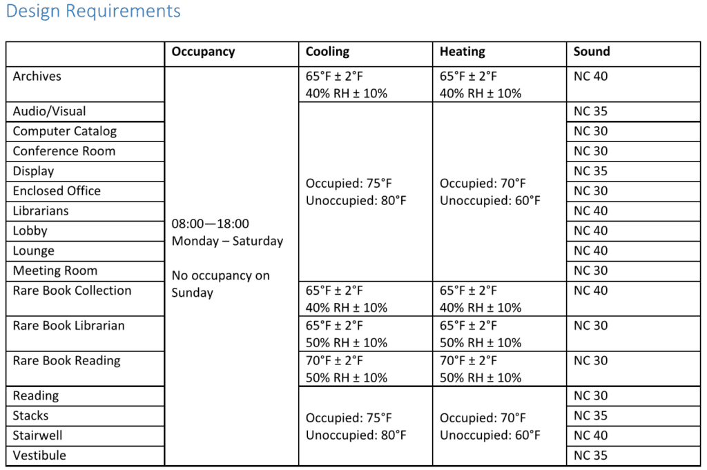
The table above is a visual representation of the Owner Requirements
Load Calculation
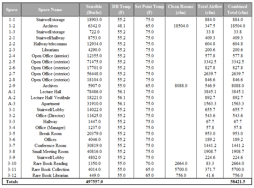
The Zoning PDF is the Drawings Section
Best Overall Design:
VRF
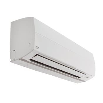
Wall mounted VRF terminal unit
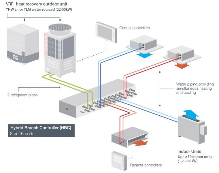
VRF system schematic
Decision Matrix
Cost Comparison
Initial Costs Comparison
Maintenance & Operation Costs Comparison
Life Cycle Cost Analysis Comparison
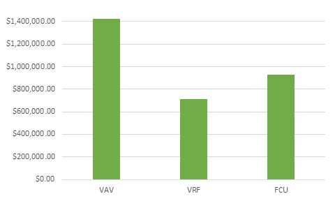
Replacement Costs Comparison
VAV Design
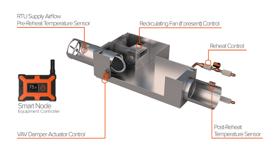
Typical VAV box with a reheat coil
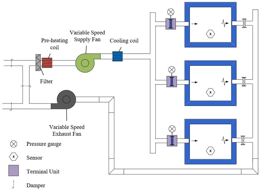
VAV system schematic
FCU Design
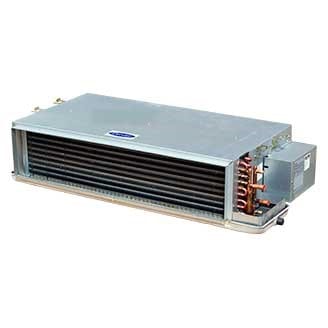
Fan coil terminal unit
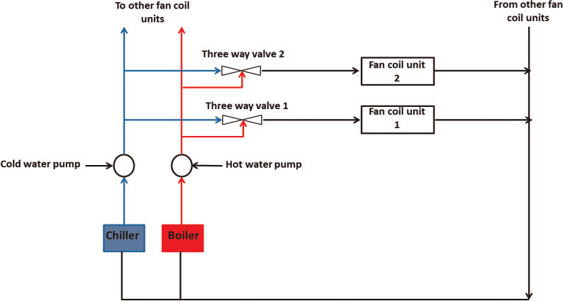
FCU system schematic
Advantages and Disadvantages
VRF
VRF applications can be used with most, if not all, different types of buildings because of their versatility, so this system will not have any problems being applied to an archival storage facility. The biggest advantage of a VRF system is that since the only outside air required is the ventilation air, the operation cost is lower than an all-air system. Refrigerant has a high volumetric heat capacity compared to all air systems or split systems. Another advantage is that VRF systems takes up less space than most air-ducted systems because refrigerant piping is relatively small. Some disadvantages of VRF systems are that the equipment is expensive, and thus has a high initial cost compared to most other systems. Another disadvantage is that the branch controllers generate a lot of noise when in operation and must be placed in areas where noise can be tolerated, possibly resulting in longer piping runs and adding to the initial cost. Another drawback of VRF systems is that maintenance is more difficult because of the amount of equipment in each zone compared to other systems.
vav
VAV applications include schools, hotels, offices, and health care facilities. The archival storage facility has a multiple setpoints in the different parts of the facility, which the VAV system can easily handle because of the VAV’s system’s flexibility for different setpoints. The initial costs for this system are relatively low compared to other HVAC systems of the same capacity because the equipment used is carried by most HVAC manufactures. One major drawback of VAV system, is that the clean rooms require a lot of air changes, which will require a lot of energy to condition the air to 55 oF (required for the system to operate), especially since Mumbai’s has a hot and humid climate. Another drawback of this system is that larger ductwork is required compared to other systems. Large space requirements for ductwork is a problem because space in the building is at a premium in the archival storage facility.
fcu
Fan coil units are used in a variety of different applications because of the easy installation and high heating/cooling capabilities, meaning that there shouldn’t be any issues with applying this system to an archival storage facility. A major advantage of an FCU system is that the equipment and installation costs are low compared to the other systems that are being considered. In addition, the operating costs are low because of the energy efficient motors that are inside each of the indoor units. A drawback of the FCU system is that the maintenance of the filters and condensate trays require a lot of work because of the number of fan coil units that each zone require. If the units are not regular maintained, the system efficiency drops, and the operating costs will increase. The fan coil units are also noisy since they are physically located in the zone. To meet the NC criteria, smaller units may be required but will increase the cost of the system.
Final Decision Process
The overall purpose of this project tasked us to recommend and design the best possible HVAC System for the new fragile/important document storage facility in Mumbai, India. The building owner’s directive posed many different types of design challenges during the creative process in determining the optimal system for the new building. Our directive emphasized the importance of multiple criteria such as energy usage, thermal comfort and health, architecture synergy, cost, reliability, sustainability, and noise. The three systems were evaluated based on how well each of them can meet these said criterion.
Load calculations, building construction values, and internal loads were determined through TRACE 700. All our calculations were under the basis of ASHRAE Standards 55 (Thermal Comfort), 62.1 (IAQ and ventilation requirements), 90.1 (minimum efficiency requirements), and 189.1 (total building sustainability guidance for high performance green building design).
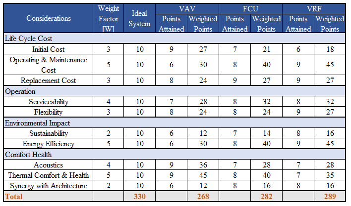
After thorough consideration and analysis of the three possible systems, the best system possible selected is the VRF system with DOAS and CAV System. With 330 points possible scored, this system scored 289 points. The VAV and FCU system scored 268 and 282 points respectively. There were many upsides and downsides to each system but overall, the VRF System ended up being the best possible choice due to several factors including cost over 50 years and effective means of cooling in the Mumbai area.
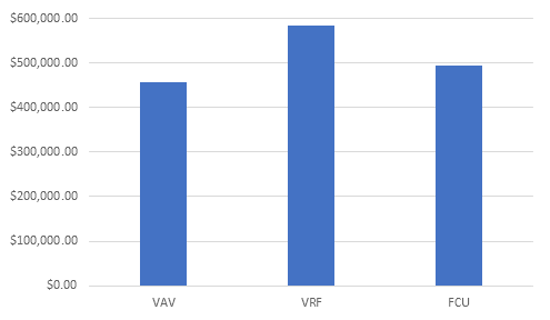
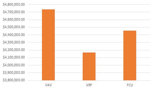
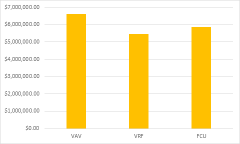
Despite having the highest initial cost, the VRF System ends up having the lowest cost overall after 50 years due to low operation cost. The VRF’s main utility usage only comes from water and electricity. The water utility usage is minimal due to having only a singular cooling tower with a low makeup water rate. There are no gas usage utilities making the operation cost significantly lower than the other two systems. The VRF system also provides the best synergy with architecture as there will be less exposed ducting than the VAV system due to using floor and wall mounted units where the piping can be hidden beneath the floor and the walls. The VRF system is one of the best possible choices for effectively handling the load due to the nature of the “outdoor” VRF Units. These VRF III W Series units can be placed indoors where they will be protected from the humid weather inside. The humidity cannot affect the performance of these units.
Final Decision
Based on the decision matrix and the supporting evidence, the VRF System is proposed as the final HVAC System selection for this building. This decision is ultimately made based on the low life cycle cost of the system, its synergy with architecture, and fantastic energy efficiency.

