Project Designer

Grant Fox
Computer Engineering Major
Likes – Gaming – Linus Tech Tips – Listening to lo-fi hip hop for literally any activity – Korean BBQ
Acknowledgements
Thank you to my senior project advisor Andrew Danowitz for advising me on this project, to my parents for helping me put together the glove’s sensors and wires, and to the CPE/EE/CSC faculty for teaching me during my time at Cal Poly.
Project Demo Video
Bluetooth Keyboard & Mouse Glove Senior Project
Project Origin
The idea for this project originated from finding an existing product called the Tap Strap 2. The Tap Strap had some issues that were commonly expressed among its users such as frequent misinput as well as undesirable mouse controls. This project was then conceived to address the issues of the product mentioned above.
Design Differences from the Tap Strap 2
- Uses pressure sensors rather than accelerometers for detecting finger taps
- Main sensors are placed at the fingertips and the back of the hand rather than only at the bases of the fingers
- Hand tilting for mouse movement compared to gesture control or requiring a table-like surface for proper mouse movement
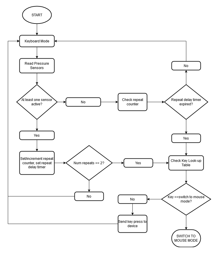
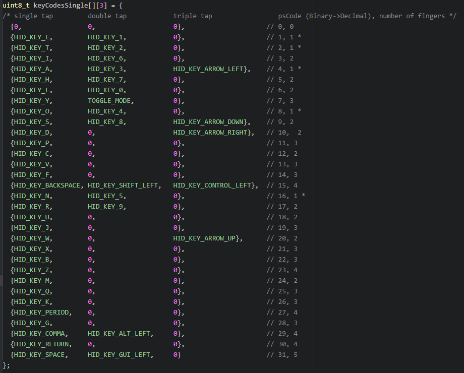
Keyboard Functionality
The keyboard portion of the glove uses pressure sensors as buttons, and based on the combination of pressure sensors activated by the fingers, the system will output a unique key depending on how many times the combination was tapped. Shown below is a table of all of the programmed keys at the time of making this webpage. Each column corresponds to all possible combinations of a specific number of finger taps: the first column is for all combinations of fingers with a single tap, the second for all combinations and two taps, and the third for all combinations and three taps. The combination of fingers tapped is converted into a 5-bit binary number, one bit for each finger, and used as the row index for this table. The number of taps is used as the column index of the table. This allows for the possibility of having much more than 2^5 unique keystrokes.
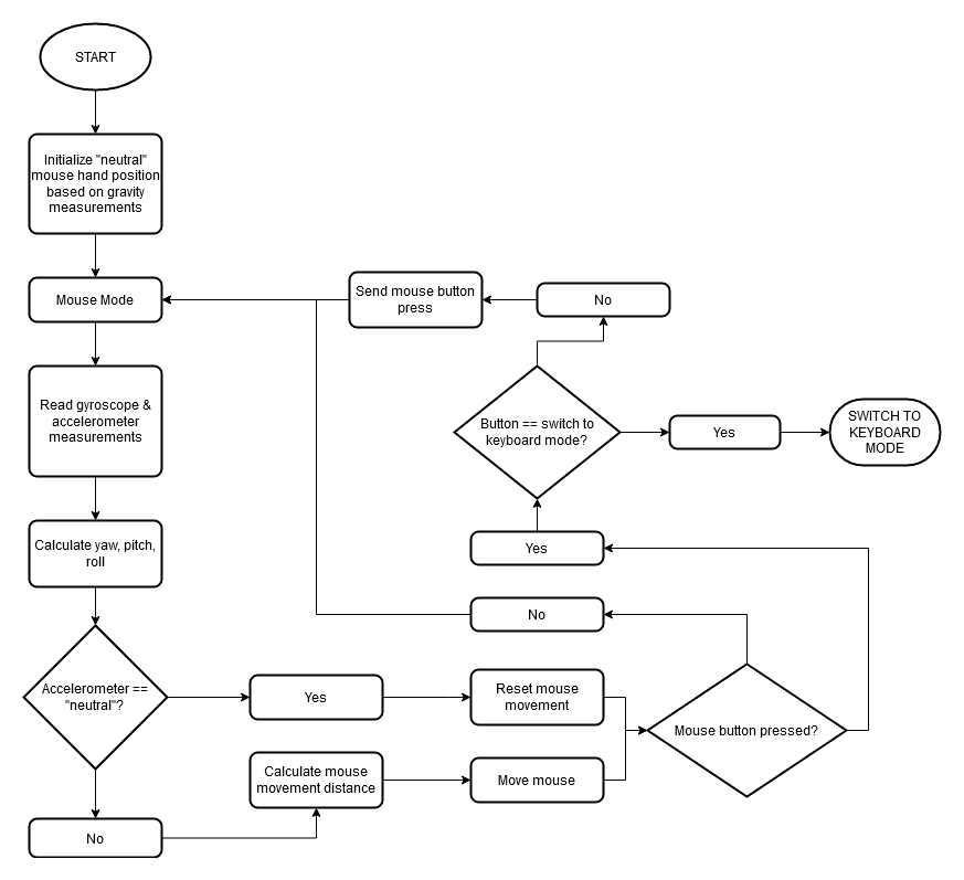
Mouse Functionality
The mouse uses the MPU 6050 accelerometer/gyroscope combo sensor and converts the glove’s physical orientation to mouse movement. More specifically, the mouse is controlled by tilting the glove similar to using a Wii remote or Joycons for games that require motion controls. Before the first iteration of the mouse code, the glove will take a measurement of the current accelerometer readings to get its orientation relative to gravity. This set of measurements will then be used as the glove’s “neutral” position. The device will then start a loop where both accelerometer and gyroscope measurements are taken first and then processed and converted into mouse movement. The integral of the gyroscope data is taken over time in order to get pitch, yaw, and roll. In order to correct drift in the rotation calculations, the accelerometer orientation vector relative to gravity is then compared to the neutral position and if their directions are within a certain threshold of being equal, the rotation values are reset. If the rotation values are non-zero, the pitch and roll are then scaled and used as the mouse Y-axis and X-axis movement values respectively. After all this, the pressure sensors are used again during each mouse loop iteration to act as mouse buttons.
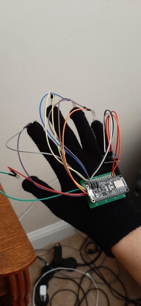
System Components
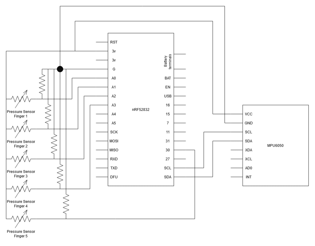
The main processor/board used is the Adafruit nRF52832. This board was chosen because the CPU, the Nordic nRF52832, can store and execute Arduino code, and Adafruit has created an associated Bluetooth Arduino library for the board. The CPU also had dedicated ADC pins, which was also a necessity in order to use the pressure sensors. Lastly, the chip also featured I2C communication capabilities which was used to communicate with the MPU6050.
The pressure sensors used in the project were the DF9-40 force-sensitive resistors. This along with the ADC pins of the main board allowed for very simple external circuitry for the pressure sensor portion of the system, requiring only one 150k resistor per pressure sensor.
Finally, the MPU6050 3-axis accelerometer/gyroscope combo sensor was used mainly since it had both a 3-axis accelerometer and a 3-axis gyroscope packed into one very small board about the size of a quarter. This combo sensor was fully capable of measuring the glove’s orientation relative to gravity, which was needed in order to get the mouse movement to work at all.
System Schematic
Software Flowcharts