Our Team
Meet the Cal Poly PROVE Lab Endurance Car Composite Body Paneling Design 2019-20 senior project team.
Brian Menard
Design Lead
Brian is a 4th year Mechanical Engineering student, graduating from Cal Poly this coming Fall. He has worked at PROVE Lab since Freshman year on both the Solar Car and Endurance Car projects, and is currently co-program manager of the Endurance Car Project. His past internship and engineering experiences have enabled him to contribute his technical knowledge on design, FEA, and machining to the project. He is eager to start building the Endurance Car this Fall.
Emma Wheelock
Finite Element and Team Lead
Emma is a Mechanical Engineering senior, graduating from Cal Poly this spring. During senior project she led the design and analysis of the aeroshell laminate simulations and helped keep the team on track. After graduation, she plans to travel the Western US and backpack in many of the national parks.
Noah Fisher
Manufacturing Lead
Noah is a Mechanical Engineering senior at Cal Poly, graduating this spring. He led the manufacturing efforts during senior project. After graduation, he plans on moving back home to Sacramento and working in mechanical design. During the Northern California winters, he’ll be spending his free time skiing the slopes of Lake Tahoe Basin.

Sarah Rutland
Finite Element Lead
Sarah is a Mechanical Engineering senior graduating from Cal Poly this spring. She led the experimental hand-calculation and finite element verification simulations during senior project. Post-graduation she is looking forward to growing her house plant collection and maybe making some travel plans to explore a few new (to her) corners of the world.
Acknowledgements
Our team would like to thank our advisor Dr. Eltahry Elghandour for his support throughout the year and Dr. Joseph Mello for his advising contribution to our project. We would also like to thank the Cal Poly PROVE Lab for their support and donation of prototyping materials.
Project Videos
overview video
Engineering video
PROVE Lab Endurance Car Aeroshell Digital Poster
Background
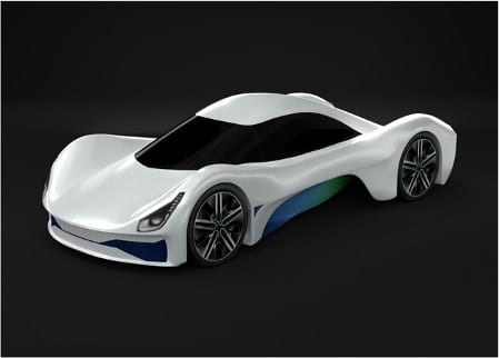
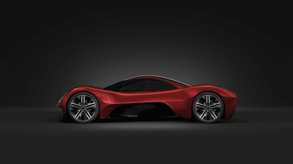
Cal Poly’s Prototype Vehicles Laboratory (PROVE Lab) is a student-run and led organization that is striving to break the solar car land speed world record using alternative energy. PROVE’s first project, Dawn, is a solar powered car designed and built from the ground-up by Cal Poly students. Using lessons learned from the solar car, PROVE Lab is making headway on its next big project, the Endurance Car. The Endurance Car, Mila, is a fully-electric, long-range sports car designed to travel over 1000 miles at 60 miles per hour on a single battery charge. Through this project, PROVE aims to push the limits of today’s technology to promote a more environmentally-conscious future for the automotive industry, while also providing skill-development and learning opportunities for Cal Poly students.The Cal Poly PROVE Lab Endurance Car Composite Aeroshell Manufacturing Project is a Cal Poly Mechanical Engineering senior project sponsored by PROVE Lab.
Problem Statement
Modified Problem Statement: Finalize the Endurance Car aeroshell panel split lines. Document the mold design process, manufacturing procedures and takeaways, material testing, and structural analysis procedures.
Original Problem Statement: Split the Endurance Car aeroshell into individual panels and design CAD models of all the molds necessary for manufacturing the aeroshell. Structurally design the individual composite panels and manufacture one final panel that can be used on the Endurance Car.
Circumstantial Note: The shift to a modified scope is due in part to the manufacturing freeze caused by COVID-19 this year. The modified scope provides PROVE Lab members with the resources necessary to carry out the aeroshell design and manufacturing tentatively starting Fall Quarter 2020.
Aeroshell Design Constraints
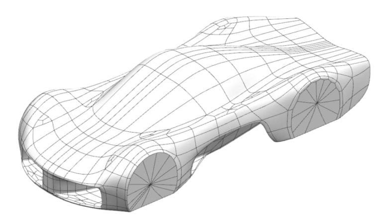
- Deflects no more than 0.25in. when subjected to a 200lbf point load.
- Puncture protection of 20 gauge steel.
- Laminate panels must be able to withstand puncture and contact loads that arise during assembly and service of the vehicle.
Aeroshell Panel Split Lines
The aeroshell was split into individual panels for manufacturing. This process proved challenging as it required planning for all phases of composite manufacturing in order to avoid future issues. It was decided which panels would be removable and the joggle connections between panels were designed.
Primary Considerations:
- Removable vs. permanent panels
- Panel joining method
- Manufacturing, integration, and assembly planning
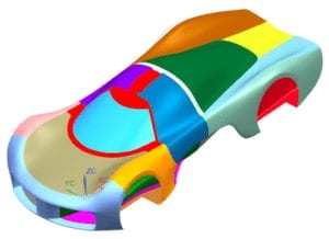
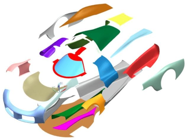
The final aeroshell panel design is comprised of 23 unique panels as shown below. The primary joining method is a joggled lip combined with adhesive glue. To maintain aerodynamics, any of the seams will be filled with Bondo, an automotive seam sealer. This technique was a success during the manufacturing of PROVE Lab’s Solar Car, but there is room for improvement with the Endurance Car.


Mold Development
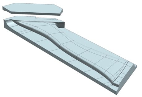
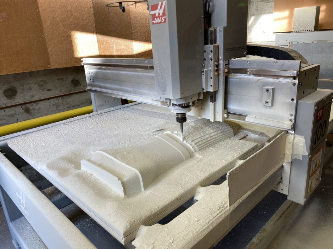
After designing the shapes of the individual panels, the team designed several of the molds needed to manufacture the composite panels. This heavily involved design for manufacturing, as the molds needed to be designed around the expected capabilities of the CNC router. Due to this manufacturing constraint, the mold design process primarily focused on eliminating negative draft angles, and creating mold assemblies such that the individual parts fit within the CNC router’s capabilities.
Primary Considerations:
- CAD design
- Design for manufacturability
- Draft angles
- Multi-part molds
- CNC machining
Concept Validation Prototype
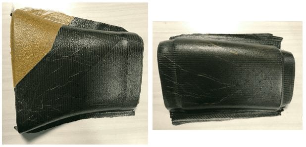
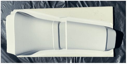
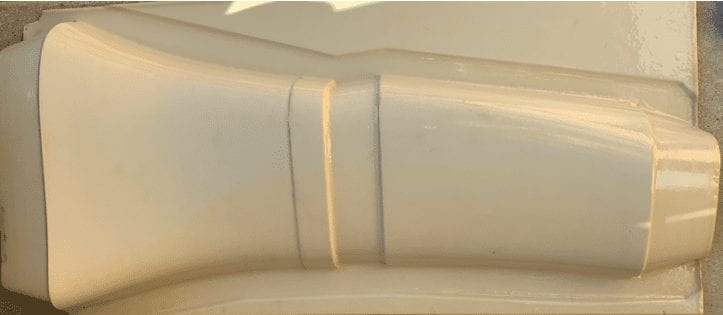
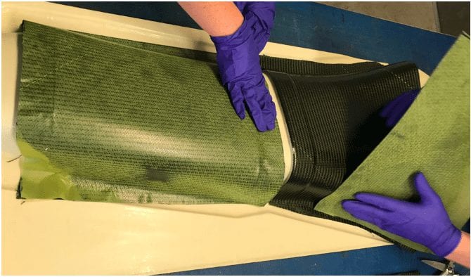
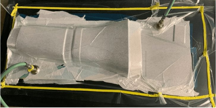
The senior project team manufactured a concept validation prototype to validate the chosen manufacturing methods and design direction. The concept prototype was designed to recreate the manufacturing processes that PROVE Lab had used in the past. The team chose to make a segment of one of the aeroshell’s front ducts and include a 1in. joggle to connect the parts.
Manufacturing Process Overview
Documentation Package
As a part of the modified project scope, an extensive documentation package has been created to help the PROVE Lab move forward with the manufacturing of the Endurance Car aeroshell when permitted to do so by the university. This documentation package will be made accessible to PROVE members.
Documentation Package Contents:
- Mold Design Guide
- Manufacturing Takeaways Document
- FEA Procedures Guide
- Composite Material Testing Guide
Engineering Analysis
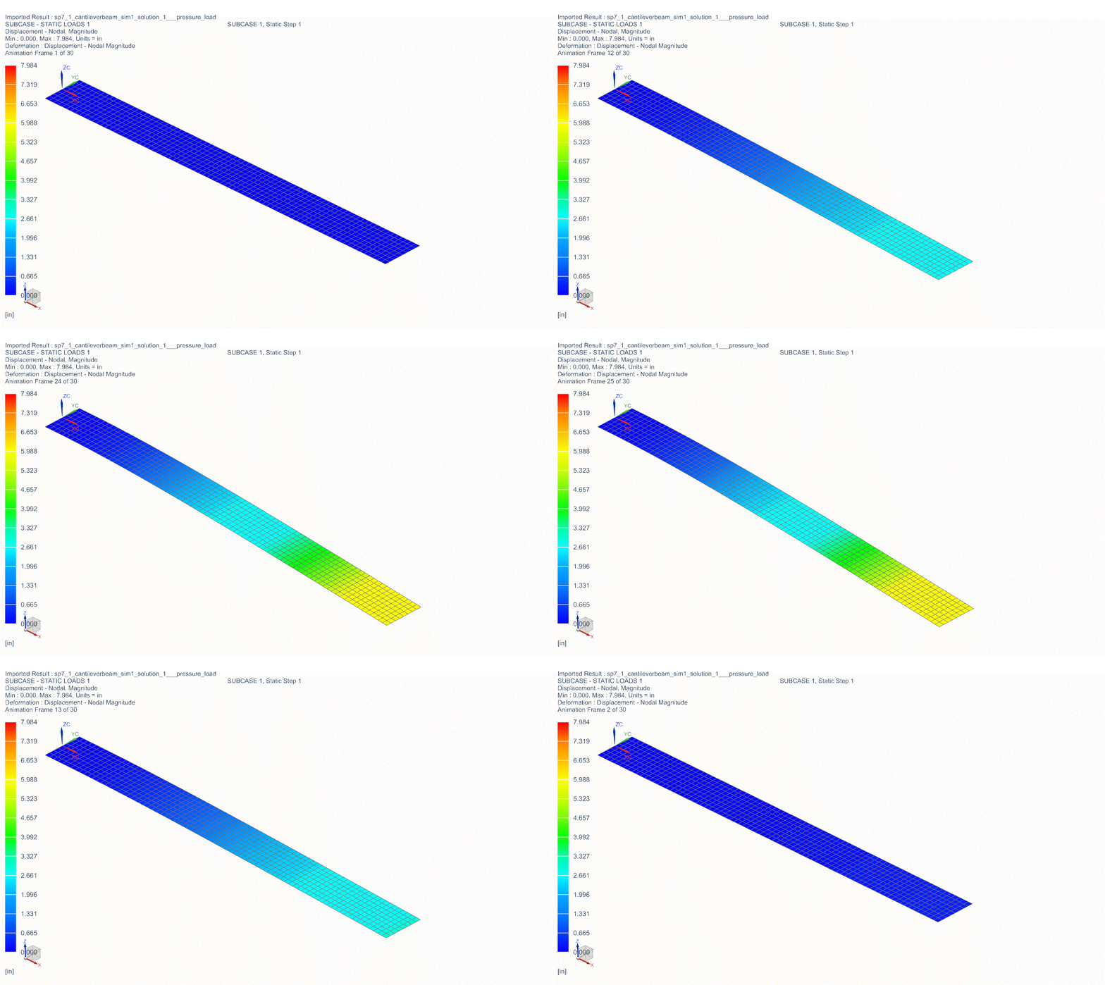
Cantilever Beam Model: To aid in verifying any FEA results related to the project, hand calculations were compared to FEA results for a simple composite cantilever beam model. Classical composite analysis was performed on a 1in. x 10in. composite cantilever beam model with a 3.58 lbf/in. distributed linear load. Dr. Mello contributed the setup MatLab script for this model. An FEA model of this beam was made using the same material properties, boundary conditions, and loading. Tip deflection results were compared to the deflection results of the MatLab script. The tip deflection results for the beam theory model and FEA model have a percent error of 3.74%.
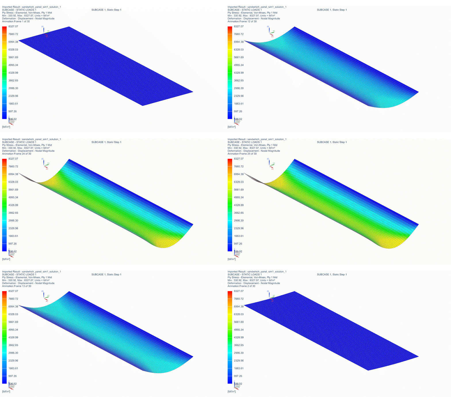
Sandwich Panel Model: Similarly to the cantilever beam model, a sandwich panel model comparison test was done to aid in verifying FEA results. A MatLab script contributed by Dr. Mello modeled a 3ft. x 10ft. aluminum honeycomb core sandwich panel with fixed translational boundary conditions along the two 10ft. edges. A 50psf pressure load was applied to the face of the panel. The maximum deflection result from the FEA model was compared to the maximum deflection result from the MatLab script. The maximum deflection results for the composite / plate theory model and FEA model have a percent error of 0.942%.
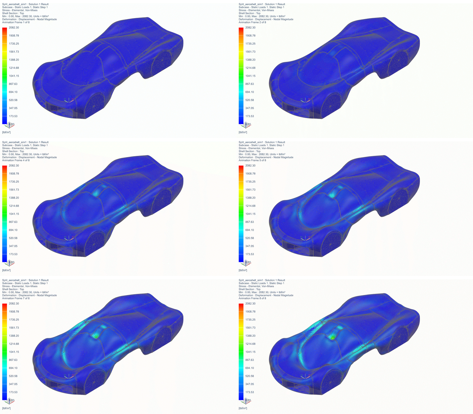
Aeroshell FEA: As a whole, the aeroshell was modeled as an infinitely-thin plate in the FEA solver. The panels were exported as groups within the entire aeroshell simulation. By exporting certain groups of panels, the boundary conditions would stay consistent for all the panels and it best represents how the panels would react when subjected to loading. Each individual panel was meshed separately and all of the meshes were connected together with the FEA solver’s edge-to-edge gluing function to simulate the joggle bonding method.

Experimental Material Testing
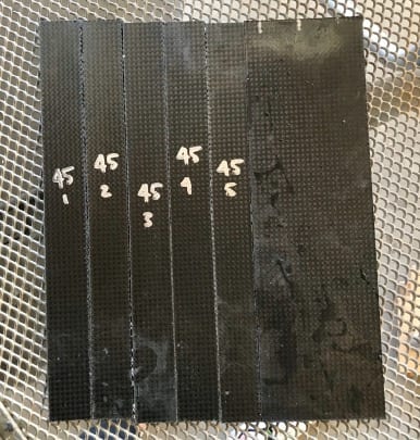
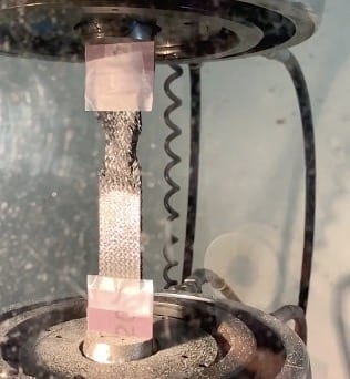
The senior project team manufactured a series of plain weave carbon fiber tensile and in-plane shear test coupons. One +45/-45° coupon and one 0/90° balanced coupon were each loaded in tension with the purpose of gathering experimental load-deflection data.
Conclusion / Future Recommendations
In conclusion, the team was able to fulfill our sponsor’s need of designing a panel manufacturing process, despite engineering challenges and a manufacturing freeze. We anticipate the resources that the senior project has compiled will allow PROVE Lab to begin manufacturing the panels with a clear cut process for design, manufacturing, and verification.
The senior project team recommends that the PROVE Lab members rely on the information and guidelines in the documentation package to move forward with the Endurance Car aeroshell build tentatively schedules for Fall Quarter 2020.

