Our Team - Up a Creek

Our team, Up a Creek, worked together with the propulsion team, Without a Paddle, to design and build a solar powered boat for the California Solar Regatta Competition. We pride ourselves in our teamwork, communication, and good snacks at meetings.

Torrey Duncan
Turbulence Torrey
Torrey focused much of her time on designing the hull, particularly the pontoon shape. She performed drag analysis to predict the performance and collaborated with the propulsion team.

Kyle Kreitzman
Kilopascal Kyle
Kyle’s work was focused on the bridge connecting the two pontoons and overall system integration. He worked hard on manufacturing plans and designed custom brackets for the water jet.

sean neuman
solidworks sean
Sean did the heavy-lifting of the team’s CAD modeling. He did much of the design work on the bridge and spent hours on the final CAD assembly. His work and accurate bill of materials were crucial before acquiring materials.

andrew offhaus
epoxy andrew
Andrew was a key contributor to the manufacturing of the hull, specializing in pontoon creation. He spearheaded pontoon manufacturing and plans to return in the fall to complete the wet layup of the hull.
Acknowledgements
We’d like to thank our advisor, Dr. Brian Self, the ME Department, and MESFAC for their support on this project. Without them, this project would not have been possible.
Project Videos
Team and project Overview
TEchnical Overview
Our Project's Digital Poster
Race Overview
Problem Statement
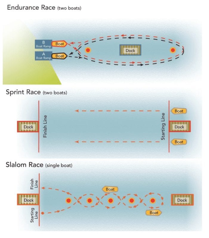
The SMUD Organization developed the Solar Regatta Competition to teach students about solar electricity and sustainable energy. Our Cal Poly Team needs a fast, nimble, low drag boat to compete in the events hosted on the lake. The boat must be designed in coordination with the propulsion team and piloted by an individual.
Design Constraints
- Maximum dimensions: 20’ x 8’ x 5’
- Use provided solar panels
- Create a watercraft that is both fast and agile
Design Concept
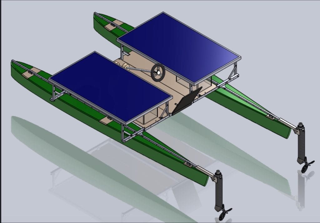
- A catamaran style design was chosen for ease of integration with the propulsion team, manufacturability, and speed.
- The pontoons are connected with a modular aluminum bridge. This will allow for testing ideal width and center of mass for performance on the water.
- Above is a picture of our initial concept. After further analysis, we determined that the pontoons could be far more slender
Design Process
A catamaran-style hull was selected over a traditional mono-hull boat, kayak, or canoe due to both its high speed and stability. The volume, length, and shape of the pontoons were driving factors in both the weight capability and performance of the entire catamaran, so multiple iterations explored different degrees of chine, rocker, and waterline. Our top priority was ensuring that the submerged portion of the pontoon would have sufficient volume to float the bridge, solar panels, and pilots.
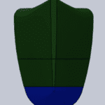
Key Pontoon Characteristics:
- low rocker
- soft chine
- high prismatic coefficient
We decided to weight top speed higher than maneuverability early on in the design process. Later interations transitioned towards shorter, lower-volume pontoons.
The flat top and bottom, along with the sharp edge features allowed us to shorten manufacturing time. We utilized a hot-wire cutter rather than a Shop-Bot CNC mill.
Sponsors


A special thank you for funding and support to the Sacramento Municipal Utilities District (SMUD) and the Cal Poly Mechanical Engineering Department.
Analysis
Much analysis was conducted on this design, ranging from simple static analysis to complex drag analysis.
The bridge was analyzed using simple beam-bending calculations. Each of the two bars in the bridge was rated to individually support the full load of the pilot with a 1.7 factor of safety.
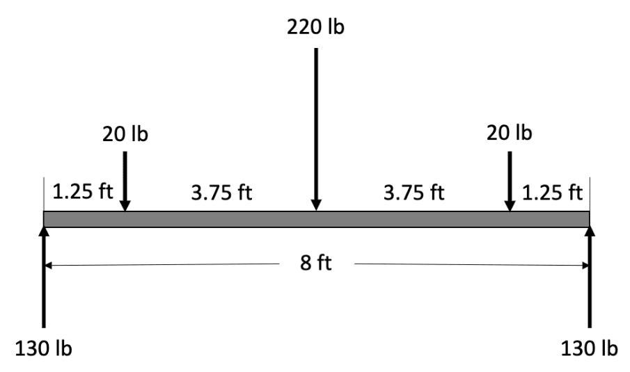
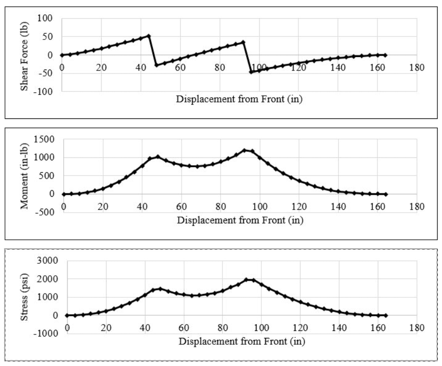
To determine the number of fiberglass layers, the pontoon was divided into 4-inch intervals that were assigned distinct section properties based off the cross-sectional geometry. This was assuming the fiberglass would create a hollow rectangular shell. These cross-sectional properties were then combined with the bridge reaction loads and a buoyancy load derived from the individual volumes of each pontoon interval to create a simplified beam analysis.
With 6 oz fiberglass, it was determined that the stress in the material would be orders of magnitude below its yield strength. The number of layers of fiberglass desired then became a function of impact and abrasion resistance, not of structural integrity.
Pontoons:
Two analyze the pontoons we performed both maximum hull load analysis and drag analysis. First, we wanted to ensure the hull could support the necessary weight, which our first design concept greatly exceeded. We realized the pontoons were far too large and adjusted dimensions accordingly. Our final design can displace 2.72 ft^3, which supports 340 lbs at the desired waterline.

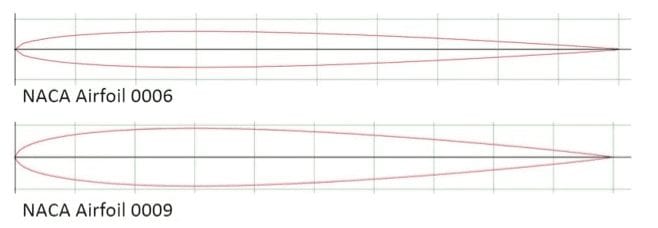
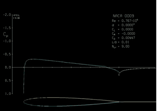
Next we used a tool called XFOIL, which was developed by MIT, to quantify the drag on the hull. Extensive research has been done on NACA airfoils so we chose this shape to reduce viscous drag as much as possible. The results showed extremely low drag coefficients, only leaving the drag due to external factors and the above water frontal area to slow us down, only leaving the drag in the air and from the waves unknown.
Manufacturing Process
The manufacturing of the hull can be broken down into two primary assemblies: the pontoons and the bridge.
Pontoons:
The pontoons are created out of permanent foam molds wrapped in fiberglass via a wet layup (very similar to how surfboards are made). To create the pontoons, large sheets of insulation foam were glued together then shaped using a hot wire foam cutter. Each pontoon was created in two parts that were then glued together using dowels. Cavities were cut in the top of each pontoon, and custom plywood inserts were placed to allow for the bridge to be mounted. The project was suspended only days before the the pontoons were to be wrapped in fiber glass and epoxy resin.
Bridge:
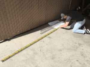
The main bridge was easily manufactured due to its simple and modular geometry. Work began by cutting all required bridge components to the desired length with an aluminum cutoff saw. Holes were then marked and drilled on the square aluminum tubes at various locations and all drilled with the same size drill bit. The wooden platform to support the pilot was then drilled out to match, and everything was assembled with ¼-20 hardware. The manufacturing and assembly of the bridge was greatly simplified by the design-for-manufacturing and design-for-serviceability goals set out by the team.
Custom Components
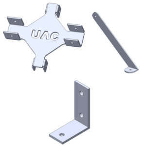
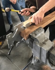
In order to improve the modularity of the boat, several custom aluminum brackets were designed to join various bridge pieces. Two simple brackets were designed to mount the solar panels, both of which required a waterjet cut and a bend using a finger break. A more complex bracket was deigned to join the pontoons to bridge structure itself, which was waterjet and then bent by hand using a vice, a mallet, and a variety of wood cutoffs. This bracket was our team’s proof of concept prototype during our design stages and worked perfectly.
Design Verification
Test Plans To Be Conducted:
- Speed test: a key indicator of success in this project is max speed of the boat. To test this we will place a phone with GPS tracking to determine the maximum speed.
- Turn radius: turn radius is very important to being competitive in the slalom portion of the race. To test this we will attach turn about a buoy and measure the distance to the center of the boat
- Watertight: if the boat is not watertight it will sink. This is a visual inspection after every time that it is in the water looking for places where water may be penetrating the fiberglass.
Final Design
Final Design Features:
- Two 14 ft pontoons
- Aluminum tubing bridge
- Middle Brackets
- Fastener connections
- Solar Panel Mounts
- Plywood pilot area
- Plywood inserts for bridge-pontoon interface
- Propulsion attachment bars
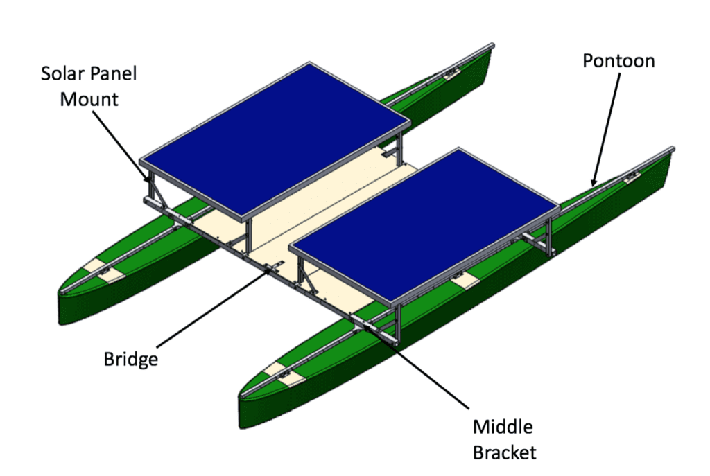
The last iteration of the catamaran hull can be divided into four distinct subassemblies: the pontoons, the middle brackets, the bridge, and the solar panel mounts. Custom angle irons screwed into the pontoons’ wooden inserts secure aluminum square tubing across the entire 14’ length of the pontoon subassembly. The custom, waterjet aluminum middle brackets serve as a modular interface between the pontoons and the bridge, allowing for subtle adjustments to the catamaran’s beam width and the bridge’s relative position along the length of the pontoons. In order to minimize the amount of the pilot’s shadow that strikes the top of the panels, the solar panel mounts utilize custom brackets to safely elevate the panels roughly one foot above the bridge.
Future Work
Due to the COVID-19 Pandemic, the project was brought to a halt prematurely, preventing our team from completing the manufacturing of the project. The competition has been postponed to 2021 and a new senior project team is picking up where we left off. We are in close communication with this new team and hope that a couple members of our team can return in the fall to assist with completing manufacturing. Future work includes:
- Wet layup of pontoons
- Finalize design of solar panel mounting brackets
- Testing above and beyond that stated
- Final assembly of boat
- Compete in 2021 California Solar Regatta
Additional Photos:
Build phase
Final Remarks
This project provided our team with a unique opportunity to learn how to take on a challenge we may or may not have been prepared for. None of us had prior boating knowledge or manufacturing experience of this scale, but through background research, interviews, and hands-on work we were able to be successful. A great team dynamic was key to this success and made this project an wonderful experience.
Although unfortunate we could not complete our build process, we wish the next Cal Poly Solar Regatta Team the best and hope we have provided a strong foundation for them to build upon. Solar Regatta 2021 should be ready for record-breaking speed!

