Our Team
We are graduating seniors from the HVAC&R program in the Mechanical Engineering department. This hands on project gave us the opportunity to apply design, build, and HVAC&R concepts to a real world application.

Raymundo Calderon-Robles
Controls
Santa Rosa, CA
Configured and programmed chamber control system including panel layout.
Raymundo will be continuing his career at Southland Industries as a Project Engineer.

Hugh Gaevert
Controls Seattle, WA
Designed and constructed electronics on the control system
Hugh will be working at DMG Corporation as a Controls Engineer

Isaac Corona-quiles
research Pomona, CA
Researched the design requirements and how to satisfy our goals.
Isaac will be working for the Air Force as a Mechanical Engineer.

michael
leon
Build team
Los angeles, CA
Assisted in the retrieval of climate chamber modification supplies.

Anzi
zhu
build team Petaluma, CA
Designed and tested the humidification system for the new climate chamber.
Anzi will be working at Automated Solutions Group as a Project Engineer
Acknowledgements
Special thanks to the HVAC&R program, Dr. Jansen of the Civil Engineering department, and Carel, USA.
Project Video Presentation
HVAC&R CLimate CHamber Digital Poster
Climate Chamber Overhaul
The goal of this project was to repair and rebuild the automation system for the climate chamber in the Civil Engineering department. This included new climate control equipment, control system, and conditioning of the climate chamber. Due to the pandemic, we were unable to fully assemble and test the project.
Design Constraints
- Drying concrete samples
- Maintain temperature of 73°F ±3°F
- Maintain relative humidity of 50% ±4%
- Log temperature and humidity data for long periods of time
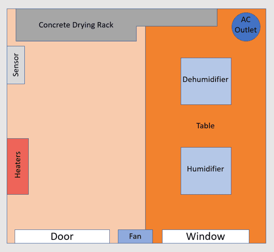
Climate Chamber Layout
Chamber
- Dimensions – 6′ x 7′ x 8′
- One door, one window
- Drying rack on rear wall
- Table on right side wall
Equipment:
- Humidifier
- Dehumidifier
- Heaters
- Fans
- Temperature and humidity sensors
- Control panel outside of room
- AC unit outside of room and with duct into room
Future Application
Dr. Peuker of the HVAC&R program wants to use the climate chamber to model the performance of an atmospheric moisture collector. The requirements for that equipment is a load of 900 Watts of heat removal and 2.5 Liters per hour of additional humidity load. The existing air conditioner will provide some heat removal and an atomizer will provide additional heat removal and all the humidity load.
Because the humidifier has a performance curve where it reaches 2.5 Liters of additional humidity below 100% humidity, the operation will only function at maximum capacity below 75% humidity.

HVAC&R Program and Carel, USA
Equipment Selection
Equipment was selected based on performance needs of removing and adding head and moisture.
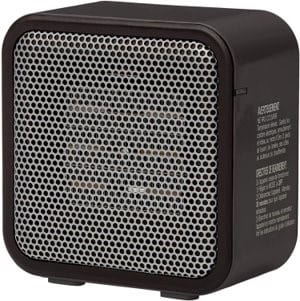
Two 500W space heaters with built-in fans to provide consistent and even heating through the chamber.
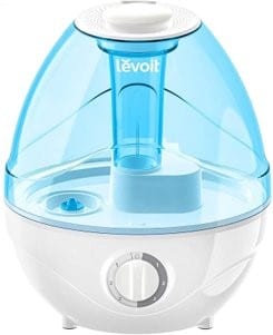
An ultrasonic humidifier to provide moisture to the space in case of dry conditions with a capacity of 250 mL/hr
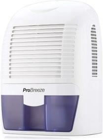
A small residential dehumidifier to remove moisture produced by drying the concrete with a capacity of 0.4 gallons.

Two temperature and humidity sensors to read conditions from several points in the room within ±0.5 °F and ±2% RH
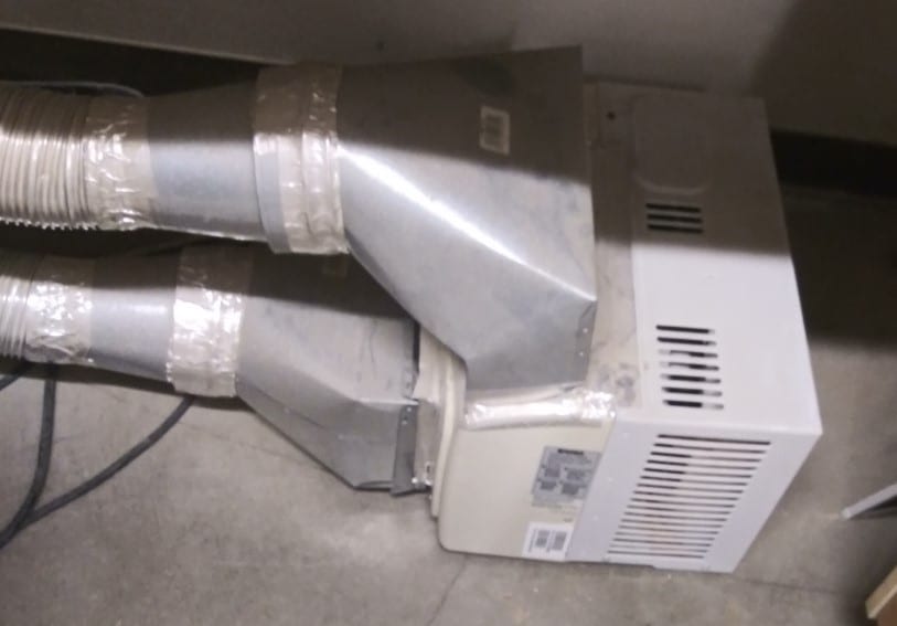
AC unit provides cooling to the space since the equipment heats up the room.
Control System
The previous control system stopped working and was outdated so the project involved replacing it with a newer, higher performance and more user friendly system.
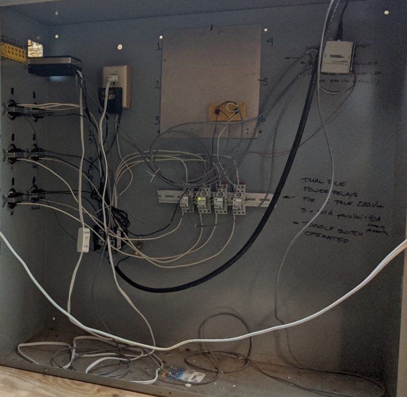
The previous control system used a National Instruments controller/logger and Omega RH controller. Using on/off control the system would trigger relays and cycle the respective equipment.
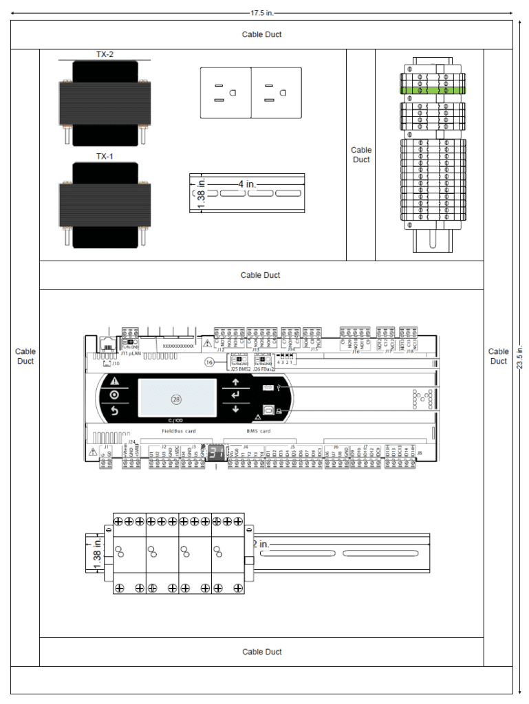
The new control system uses a Carel c.pCO programmable logic controller (PLC) to read data from Senva temperature and relative humidity sensors and cycle respective equipment using on/off control via relays.
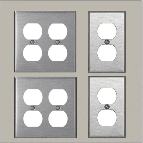
The outlet panel is located adjacent to the main control panel and is responsible for providing 120 VAC power to the equipment
Recommendations
Steps to completing the project:
- Second coat of paint (minimum)
- Outlet panel assembled and wired for operation following recommended wiring diagram
- Test A/C unit to ensure proper operations
- Test Equipment in chamber
- Restore chamber to proper setup for samples (including racks and boxes)
- Determine location of Temp/RH sensors and wire
- Run wires for sensors
- Install enclosures next to chamber and wire for operation
- Run all equipment for at least a week to ensure proper monitoring and operation
- Test data logging and determine best method for backing up logs
- Write operation and safety manual

