Project Videos
General Project Overview
Technical Overview
Our Project's Digital Poster
Problem Statement
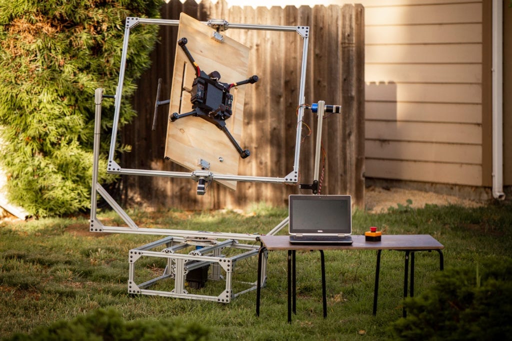
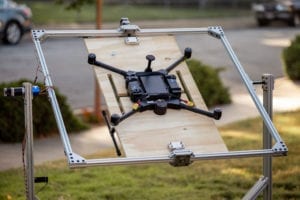
Inspired Flight Technologies would like a way to calibrate then test the calibration of their unmanned aircrafts with a more consistent procedure, as the current processes are conducted manually; this can be slow, awkward, and a potential source of error.
Design Constraints
- Angular Positional Accuracy of ±1 degrees
- Calibration run time of less than 10 minutes
- Designed to be made easily compatible with future drone designs
Conceptual Design
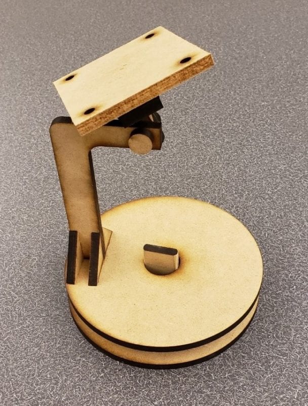
A laser cut conceptual prototype of the rotating arm design. It was not chosen as it was less balanced and it introduced a moment arm.
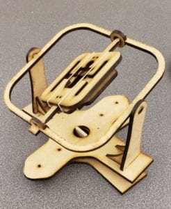
The conceptual prototype of the chosen gyroscope design. It showed the most stability in any orientation
Design Verification
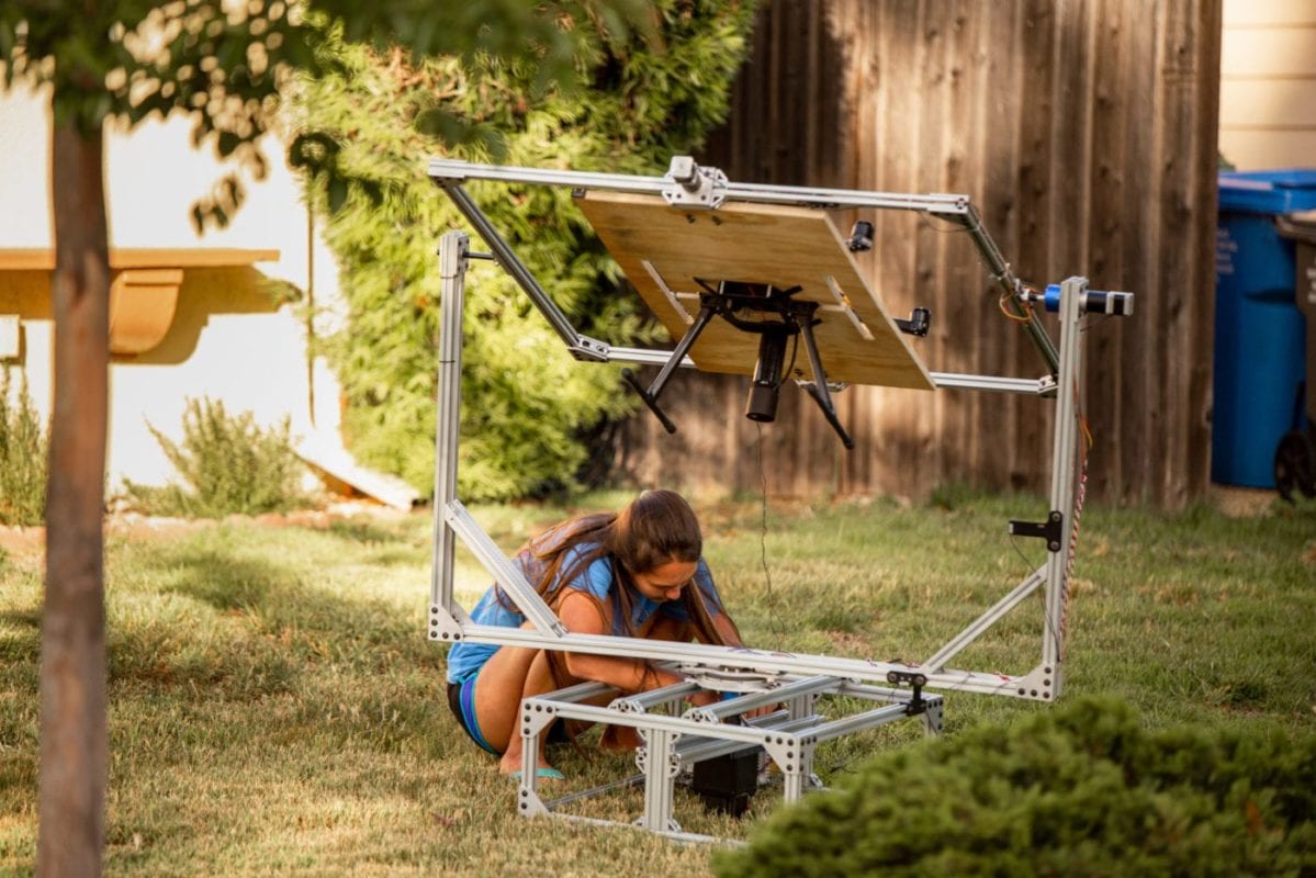
Our most important specification and the one that could be determined by a detailed test procedure is the angular positional tolerance of each axis. All other specification can be determined by inspection or a simple measurement. Due to manufacturing delays and other setbacks working with the hardware and software, we were unable to complete the full test plan. Our main focus has been creating a system that integrates with the drones software and runs the correct calibration procedure. After meeting that overall goal, we will test more detailed performance characteristics with any additional time.

This project is sponsored by Inspired Flight
Software Design
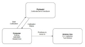
The basis of our software design is a task state machine. It is comprised of a number of tasks, each one of which has multiple states that perform a certain function.
A significant challenge in the software development was developing our code so that it can communicate with software running on the drone’s flight controller. The signals containing the drone’s current calibration state must be processed by our system and power the motors accordingly so the drone rotates to the correct orientation.
Our code runs on Arduino Uno microcontroller as well as a computer for the user interface and to connect to the drone via a telemetry module. The drone itself runs PX4 flight control software.
Manufacturing Process and Components
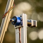
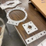
We used 8020 extruded aluminum tubing for the main structure, so most of the custom manufacturing was done to mount various components and to join the different sections of the device together.
We decided to make the most of our custom mounting plates that connected the different frame sections together out of 1/4″ aluminum due to its light weight, ease of manufacturability, and relative strength. We did this primarily in the ME shops using the water jet and the manual mills.
The smaller custom parts were made on a 3D printer using Polycarbonate filament. This allowed more complicated structures and faster fabrication times while still meeting the required strength and stiffness.
Final Design
Custom Components
- Motor mounting plates
- Drone attachment assembly
Stock Components
- 8020 aluminium frame and fasteners
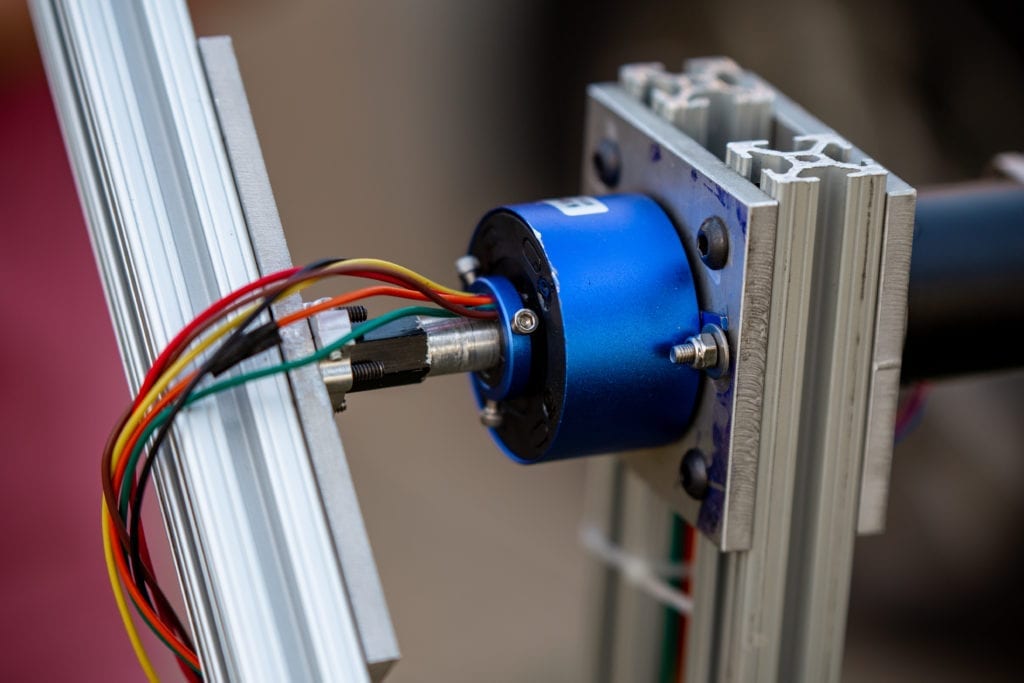
- Slip rings and other electrical hardware
The final design features corner braces in the fork for increased stiffness while rotating. The drone mounting plate was designed to be a poly-carbonate plate, but is made out of plywood due to manufacturing limitations
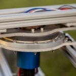
An important design feature in this project is the ability to pass an electrical signal through a rotating joint using slip rings. An image of the joint with this design is shown below.
Future Application
The purpose of this project is to add more consistency to the drone calibration process and to save Inspired Flight engineers the time required to manually calibrate each drones. We hope this device will improve calibration related performance issues and streamline the distribution process.
Recommendations
Improvements to be made if drone calibrator were to be re-designed:
- Increase the joint stiffness so there is less vibration when starting and stopping
- Use 3D printed parts to replace the water jet and machined mounting plates.
- Create more user specified options in the case of a calibration error (opposed to restarting the entire process)
Our Team
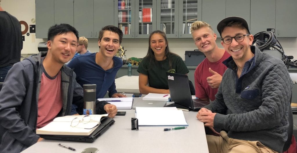
We are five Mechanical Engineering seniors at California Polytechnic State University

Jackie
Paik
Mechatronics
Jackie is from Westminster, Colorado. She loves the rock climbing, surfing, and the outdoors. She took a project management role, while still focusing on software and electronics. After graduating, she plans to go work for Lockheed Martin as a mechanical design engineer.

Matthew
Carlson
Mechanical Design
Matthew is a mechanical engineering student who is passionate about helping people, product design, pineapples, and dancing. He was involved in the design and manufacturing of the project. After doing the Blended Masters program at Cal Poly, he hopes to continue helping people and designing things.

Tyler
Van den Berg
Mechanical Design
A current employee at Inspired Flight in SLO, Tyler was committed to the success of the calibration project. He had a large part in designing and manufacturing the physical system. He plans to carry on as a Mechanical Engineer for Inspired Flight after graduation.

Ryan
Zhan
Mechatronics
Ryan is a student with a strong interest in mechatronics. He enjoys working on interdisciplinary projects and was very excited to be a part of this team. In his free time he enjoys cooking, reading, and learning new things.

Zach
Richter
Mechatronics
Zach is from Kirkland Washington and came to Cal Poly because of the high quality engineering programs. He is continuing his education at Cal Poly through the Blended Masters Program in Mechanical Engineering.
Acknowledgements
Our team would like to acknowledge certain people who supported us and were critical in the completion of this project. These people include Sarah Harding, our advisor, Eli, Marc and Martin, our contacts at Inspired Flight who sponsored and funded this project, and Charlie Refvem, who we consulted for mechatronic design.

