Our Team
Meet our team of Cal Poly students and feel free to reach out to us…

Austin griewe
biomedical engineer
Austin currently works at Applied Orthopedic Design, creating 3D pre-operative surgical plans for total knee and hip arthroplasty. He will be returning to Cal Poly for the 2020-2021 academic year to pursue a Master’s degree in biomedical engineering.
Austin can be contacted at:

Brian
Ho
mechanical engineer
Brian is a graduating senior from Cal Poly SLO majoring in Mechanical Engineering. He will be working in the aerospace industry after graduation, specializing in aerospace tooling design. Brian is from Los Angeles and enjoys playing badminton.
Daphne Shieh
electrical engineer
Daphne is a graduating senior from Cal Poly SLO majoring in Electrical Engineering. She is pursuing the power industry after graduation, with an interest in power systems. Daphne is from Los Angeles and enjoys embroidery in her spare time.
Daphne can be
contacted at:

Joseph rockwell
industrial engineer
Joseph is returning to Cal Poly for the 2020-2021 academic year to pursue his Master’s degree in Engineering Management after already having completed his undergraduate curriculum in Industrial Engineering. Joseph is from the Bay Area and enjoys playing soccer and basketball and socializing with his friends.

Nicholas krasnoselsky
biomedical engineer
Nic is returning to Cal Poly for the 2020-2021 academic year to pursue his Master’s degree in Biomedical Engineering. Nic is from Seattle, Washington and enjoys exploring the outdoors.
Nic can be contacted at:
nkrasnos@calpoly.edu
Acknowledgements
We would like to extend a special thanks to our sponsor, Dr. Anita Bagley, and Shriners Hospitals for Children for their continued support and flexibility throughout the year. We would also like to thank our advisor, Dr. Vladimir Prodanov, for his constant support and assistance to help us bring this project to fruition.
Our Project's Digital Poster
Problem Statement
Cerebral Palsy (CP) is the most common physical disability for children and is characterized by muscle stiffness, uncontrolled movements, and poor balance/coordination. Many patients with CP use walkers to support them. The Motion Analysis Lab at Shriners Hospital utilizes force/pressure platforms to obtain kinetic data but these techniques are not compatible with walkers.
Existing Design
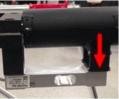
The UC Davis team’s instrumented handle is attached directly to walker handle. Force exerted on the walker is transmitted into load cell.
This design is only compatible with around 50% of walkers as it requires a round cylindrical handles and proper length.
Our Objective
To improve the load analysis performed at Shriners Hospital to accommodate more walker designs.
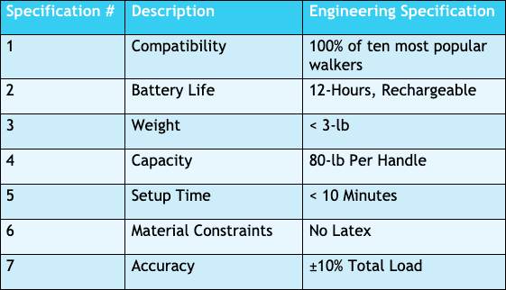
Engineering Specifications
Design Concept
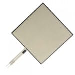
This 2×2 in. flexible sensor is capable of measuring loads up to 10,000 lbs.
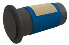
The idea of attaching the sensor to a flexible band would allow for compatibility with all walkers.
Our initial concept was centered around Tekscan’s flexible force sensor, the A502. We hoped to attach the lightweight sensor to a pediatric blood pressure cuff. Not only would the cuff be compatible with all walker handles; the velcro cuff could be easily and quickly attached.
Preliminary Testing
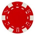
We used a poker chip as a puck on which we applied our load on a flat surface to concentrate the load.
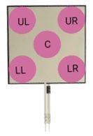
Testing different locations on the sensor to determine if there’s statistical difference in the output based on location.
We found in these test that the sensor was able to distinguish between 5-lb weight increment. However, there were significant differences among sensor locations. We modified our design to ensure that the load was equally distributed among the face of the sensor.
Manufacturing
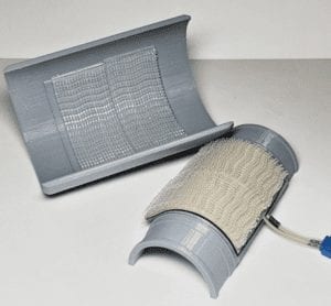
3D Printed Shells
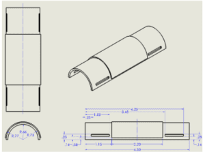
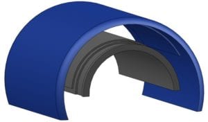
Improvements:
- Allows more force to be directly applied through the sensor
- Increased sensor accuracy (Manufacturer’s recommendation utilizing 75% of sensor area)
- Light-weight
- Still compatible with walkers and crutches

Shriners Hospital for Children
Sponsor: Dr. Anita Bagley
Advisor: Dr. Vladimir Prodanov
Electrical Layout
Voltage Output Circuit
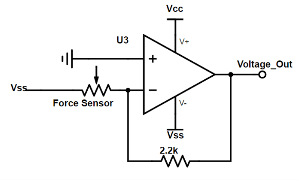
The voltage circuit shown above utilizes an inverting operational amplifier. This set-up utilizes the flexible sensor’s inverse weight-resistance relationship to provide a linear voltage output to represent the weight. The specific operational amplifier used is the uA741 from Texas Instruments.
Frequency Output Circuit
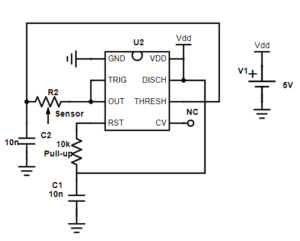
The frequency output circuit shown above utilizes a XNE7555 as a 555 timer. As the weight applied to the sensor increases, the circuit provides a linear increase in its frequency output.
Electrical Testing
Linearity Testing
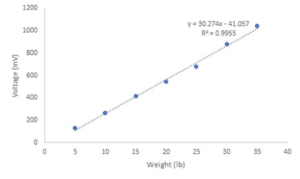
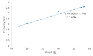
The purpose of these tests was to characterize the linearity properties of the sensors, meaning a proportional output is received from increasing input. For both circuit set ups, the sensors displayed extremely linear results.
Creep Testing
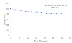
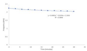
Creep tests were conducted by placing a constant load of 20 lbs. on the sensor in the shell for 30 minutes. Although there is a slight decay in the output, this is an acceptable decline due to the extreme longevity of the test.
Precision Testing
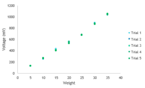
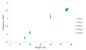
To ensure sensor output was consistently precise, we conducted 5 weight matching trials for each setup. The largest standard deviation for the voltage circuit was 15 mV while the largest deviation for the frequency circuit was less 0.2kHz.
Mechanical Testing
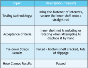
Fastener Testing
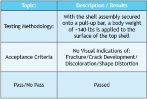
Weight Capacity Testing
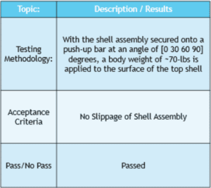
Slippage Testing
Final Design
3D Printed Components
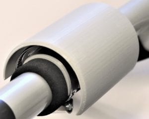
- Inner shell ID: 1.33″
- Inner shell OD: 1.57″
- Outer shell ID: 2.09″
- Outer Shell OD: 2.33″
- Printed using PLA
Other Components
- Hose clamps with turnkey used to clamp inner shell to walker
- 3M Dual-Lock tape used to connect outer and inner shells
- FlexiForce Sensor sandwiched between bottom shell and 3M tape
DAQ connection
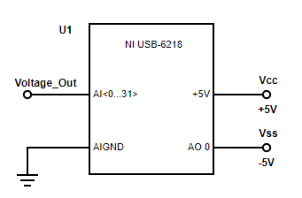
Shriners Hospital utilizes the NI USB-6218, a data acquisition device (DAQ), to control other devices in the lab. To ensure compatibility with their current lab system, we’ve designed our system to connect to their DAQ. Shown above is the recommended connection. The op-amp’s voltage output can be connected to analog input pins 0 to 31, so long as the positive input terminal is connected to AIGND. For the op-amp rails, the DAQ can also provide a +5V supply from its specified pin and a -5V supply from any of its analog output pins.
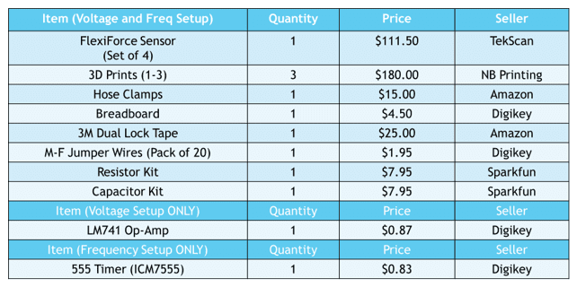
Bill of materials
Conclusion & Recommendations
- Further testing with greater loading
- Fatigue testing of 3D Printed Shell
- Test with Cortex connection for wireless compatibility
- We recommend using the voltage circuit as it’s easier to set up with the ADC and its results are more accurate
- Order a PCB to eliminate the need for loose wires

