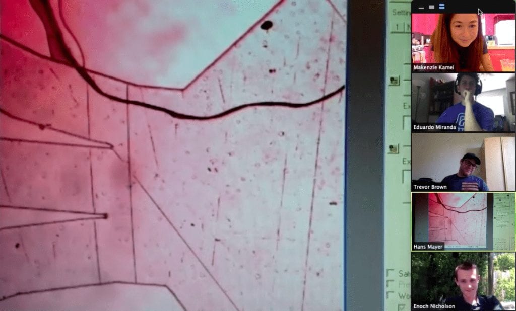
Inverted Fluorescence Microscope

Our team's IFM Design Verification Prototype in the Cal Poly Microfabrication Laboratory.
During the 2019-2020 Academic Year, the Inverted Fluorescence Microscope (IFM) senior project team designed, assembled, and conducted partial verification testing of a proof-of-concept microscope for the Cal Poly Microfabrication Laboratory. To expand the use of fluorescence microscopy accessible to undergraduate students, the team produced a low-cost inverted microscope capable of brightfield and fluorescence illumination, repeatable electronic actuation of the microscope stage, and imaging of a sample under stagnant conditions.

Our Senior Project T.E.E.M.

Trevor Brown

Trevor Brown

Additive Manufacturing Lead

Trevor took the lead in the fabrication of components requiring additive manufacturing. All of the brackets that mount the actuators and return springs on the stage were 3-D printed, in addition some select optical mounts. The 3-D printed parts allowed for a low-cost and iterative design.

Eduardo Miranda - Electronics Lead

Eduardo Miranda

Electronics Lead

Eduardo led the electronics portion of the project, creating a control system to move the stage and precisely locate the sample.  The stage is controlled by an Arduino and two actuators to move freely by the user through use of a joystick or numerical values entered to a set distance.

Enoch Nicholson

Enoch Nicholson

Project Manager

Enoch was in charge of the mechanical design of the microscope stage subsystem. He designed the actuation system brackets and acted as the point of contact for outsourcing the fabrication of the stage plate. He also managed the project’s scheduling and deadlines.

Makenzie Kamei

Optics Lead / SPOC

Makenzie led the team in optical design, researching and administering the selection and purchase of microscope optical and opto-mechanical components. She also managed the integrated system CAD model and acted as the single point of contact with the team project sponsors.

Acknowledgements

We would like to express our thanks to our project sponsors, Dr. Hans Mayer and Dr. Benjamin Hawkins for their guidance and support throughout the design process, for their patience and willingness to remotely assemble and test our final microscope prototype, and for providing us with an invaluable learning experience in engineering design and collaboration.

We are also extremely grateful for the patient counsel of our Senior Project advisor, Peter Schuster, who graciously guided us through the Engineering Design Process. We feel well-equipped with the skill set we have acquired and are confident in our ability to make influential contributions in our future industry endeavors.

Our Project Videos

GENERAL VIDEO

ENGINEERING VIDEO

Our Project's Digital Poster

PROBLEM STATEMENT

Design, assemble, and test an inverted microscope capable of brightfield and fluorescence imaging for use in the Cal Poly Microfabrication Laboratory. Utilize both commercially-available and custom manufactured parts to provide a low-cost, modular device to serve as a platform for student research projects. Achieve electronic actuation of microscope stage while maintaining critical travel and parallelism specifications.

Functional Decomposition of our project, providing a visual means of understanding project goals and requirements.

STAGE DESIGN

Actuation

The microscope stage, fitted with PLA brackets used to support and secure the actuators.
Microscope stage, fitted with PLA brackets used to support and secure the actuators.

The microscope’s X-Y motion system uses a heavy-duty stage purchased online. The stage came mounted on linear rails. Our team outfitted it to be controlled using linear actuators. These actuators are attached to the stage using 3D printed PLA brackets. To simplify manufacturing, the brackets are designed to fit the existing mounting holes on the stage. 

Spring Return

The actuators only apply a force in one direction. To enable motion back and forth, our team designed a spring return system. The X and Y axes each have a single extension spring. These springs were selected to keep the system load below the actuators max force threshold. 

Stage Plate

Model of the machined and anodized aluminum stage plate for sample retainment.

Our team designed an overhung plate to hold samples for observation, allowing ample room for experimentation and modification. The plate bolts to the top of the X-Y stage and features a large, recessed viewing window to facilitate custom apertures. It also has multiple mounting holes for stage clips to retain the sample or experimental devices.  

FINAL DESIGN

CAD Model

Full Solidworks model of the final microscope design, including optics, stage, and frame subsystems.
Full SolidWorks model, exploded to show subsystems.
Exploded view of model to show subsystems, including stage, brightfield and fluorescence illumination, z-axis focus, imaging, and microscope frame.

We used SolidWorks to model our final microscope design, determine tolerances to meet our design specifications, and provide our sponsor with comprehensive visual instructions for remote assembly.

Verification Prototype

Final IFM Design Verification Prototype (May 28th, 2020).
Final IFM verification prototype, as completed on 05/28/2020.
Actuator placement on microscope sample stage (May 28th, 2020).
Actuators attached to stage on backside of IFM.
Microscope optical train, aligned for brightfield testing.
Microscope optical train, aligned for testing.

In our final Spring Quarter remote assembly session, we aligned optical components underneath the stage, evaluated the microscope’s brightfield capabilities, and tested stage travel in both Joystick Mode and Programmable Path Mode.

MICROSCOPE CONFIGURATION

The inverted microscope configuration allows for additional space above the sample, in comparison to an upright microscope with an objective above the sample. When researching microfluidics, extra space is advantageous since the stage can become crowded with tubing and connectors. 

Comparison of standard upright and inverted microscope configurations.

OPERATION MODES

BRIGHTFIELD

Light path of the microscope in brightfield mode, from illuminator to camera.
Light path of microscope operating in "brightfield mode," from illumination source (top right) to camera image plane (bottom left).

Brightfield illumination is a standard function of essentially all microscopes. Prior to operating the microscope in fluorescence mode, the user first must get the sample within the field of view of the objective and focus on the desired sample features with brightfield.

FLUORESCENCE

Excitation light path, from LED illumination to excitation of indicator dye in sample.
Emission light path of the microscope operating in fluorescence mode, sample emission to camera image plane.
Emission light path, from sample fluorescent emission to camera image plane.

Operation in fluorescence mode requires additional specific components:

  • Single-wavelength LED
  • Fluorescent indicator dye
  • Emission filter

All components must be compatible, specified by the excitation and emission wavelengths of the chosen indicator dye, or fluorophore. A dye will excite at a rated wavelength, and emit at a slightly longer wavelength.

PRELIMINARY TESTING

Enoch tests the strength of our PLA brackets, using a welded fixture to mimic the actuator, ratchet straps to apply force, and a spring scale to measure.
Enoch tests the strength of our PLA brackets, using a welded fixture to mimic the actuator, ratchet straps to apply force, and a spring scale to measure. All brackets withstood twice or more of the expected load in operation.

REMOTE ASSEMBLY

Student-instructed remote assembly of microscope verification prototype via Zoom conferencing.

Our team, during the final quarter of senior project, held weekly remote assembly meetings with our project sponsor to complete our verification prototype. During these sessions, we used our CAD model to provide visual as well as verbal instruction.

DESIGN VERIFICATION

To verify our design, we tested our IFM’s ability to resolve an image in brightfield mode, obtaining clear images of a microfluidic chip with ~1mm features. Precise location of the sample was successful in both Joystick Mode and Programmable Path Mode, and the microscope maintained sharp focus along 50mm of travel in each direction.

Brightfield image of a microfluidic device (and a hair) using our IFM Verification Prototype (May 28th, 2020).
Successful brightfield image of a PDMS (Poly-Di-Methyl-Siloxane) microfluidic device (and a hair).

ENGINEERING SPECIFICATIONS

This table shows the engineering specifications that drove the design process of our inverted fluorescence microscope, and whether these specifications were able to be verified and attained during prototype testing.
* Verification: Possible and Complete (PC); Possible and Incomplete (PI); Impossible (I)

The above table lists the Engineering Specifications that drove our design process, and whether is was possible to verify and attain these target values during final prototype testing.

ELECTRONICS

Actuator test board - Arduino programmed to control the linear actuators that advance the stage in the X and Y-directions.

Coding

Sample location can be controlled using two modes: Joystick and Programmable Path Mode. In Joystick Mode, the user can manually control sample position. In Programmable Path, coordinates can be entered to travel to a precise location.

  • Initial Mode
    • Zeroes the actuators
  • Joystick Mode
    • Operates in the Cartesian coordinate system
    • Speed is regulated through encoder counts
    • Limit switches safeguard the actuator from over-extrusion or over-retraction
  • Programmable Path Mode
    • Two prompts: (1) selecting an actuator to manipulate and (2) enter a number of encoder counts with a designated threshold

Hardware

  • L293D Motor Driver
  • Newport 850G – HS Actuators
    • 0.605 μm encoder resolution
    • Max. 12V operation
    • 18-lb. rated load
  • Arduino Mega
  • DC Power Supply

MANUFACTURING

This is the 3D printer available for our project use in the Clean Room. We used it to print our PLA stage brackets, as well as some of the less critical frame and opto-mechanical fixtures.
A first iteration of the PLA stage brackets that we printed using the 3D printer in the Clean Room.

The stage brackets as well as few of the optical and frame components, were 3-D printed in PLAallowing for design iteration and ease of manufacturing.

RECOMMENDATIONS

  • Fabricate sample to test microscope in fluorescence mode
  • Purchase indicator dye in conjunction with compatible emission filter to operate the microscope in fluorescence mode.
  • Develop a caged optic system or 3-D printed enclosure for the optical train to maximize light transmission.
  • Purchase an infinity-corrected objective of higher magnification (original design target was 10X) with a longer working distance.
  • Add an objective turret for microscope use with objective lenses of different magnifications and working distances.
  • Anodize the stage plate to reduce reflectivity, thereby increasing light transmitted to the camera
  • Program a third actuation mode to execute sequences of commands

CONCLUSIONS

The microscope will now find its home in the Microfabrication Laboratory, for undergraduate student use and development.

Our sponsors are appreciative of our work this year to provide Cal Poly with another valuable and cost-reduced research instrument. We are proud of what we were able to accomplish and are excited to see our product in use to further the education of future engineering students.

IFM Senior Project team and sponsor in high spirits after a successful day of testing (May 28th, 2020).
Brightfield image of a microfluidic device (and a hair) using our IFM Verification Prototype (May 28th, 2020).
IFM final design verification setup in the Cal Poly Microfabrication Laboratory (May 28th, 2020).
Final IFM Design Verification Prototype (May 28th, 2020).
Actuator placement on microscope sample stage (May 28th, 2020).
Electronics subsystem to allow user to precisely control sample location (May 28th, 2020).
Design Verification Prototype optical train, aligned and ready for testing (May 28th, 2020).
IFM senior project team making progress via Zoom (Spring 2020).
Student-instructed remote assembly of verification prototype (May 2020).
Actuator test during remote assembly session (May 2020).
PLA preliminary test setup to determine strength of stage brackets.
Experimental setup for stage pull test to determine the lower bound for sizing the springs.
MATLAB plot showing where thee chosen springs fall within system constraints.
Conceptual CAD model (Fall 2019) - We've come a long way!
Concept prototype (Fall 2019).
Team photo from our first senior project "meeting" at Shalimar Indian Restaurant, sans Enoch's face (October 2019).
Previous
Next

Have a Question About this Senior Project?

Send an email to pschuste@calpoly.edu to be connected with the project team. Please include the title of the senior project you’re inquiring about in the subject line.

Interested in Sponsoring a Mechanical Engineering Senior Project?

Visit our Sponsorship Page to learn more!

Check Out More Projects!

Visit our ME Senior Projects Page to view the latest Mechanical Engineering senior projects from the class of 2021!

Share

Share on facebook
Share on twitter
Share on linkedin