
BRAD ALBRIGHT
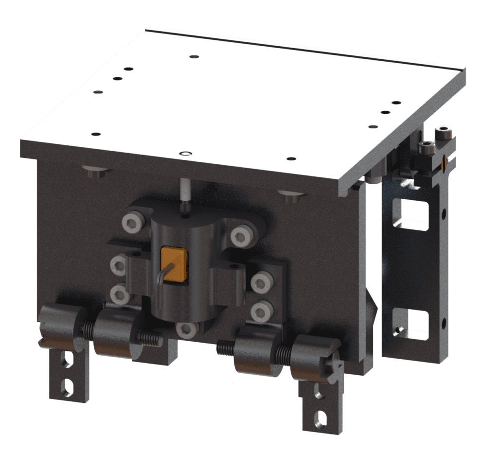
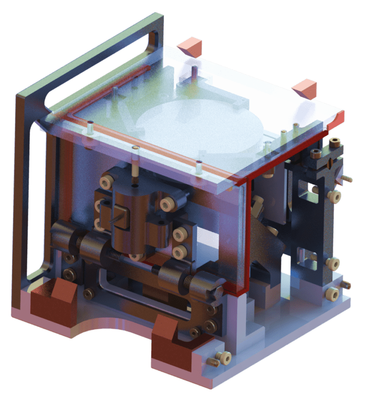
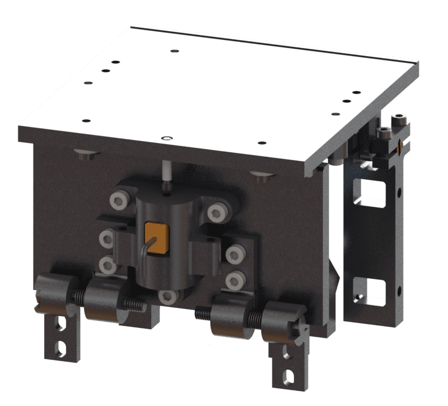
INSTRUMENTATION FRAME LEAD DESIGNER

colin harrop
orbital deployment simulator lead designer

NICO armenta
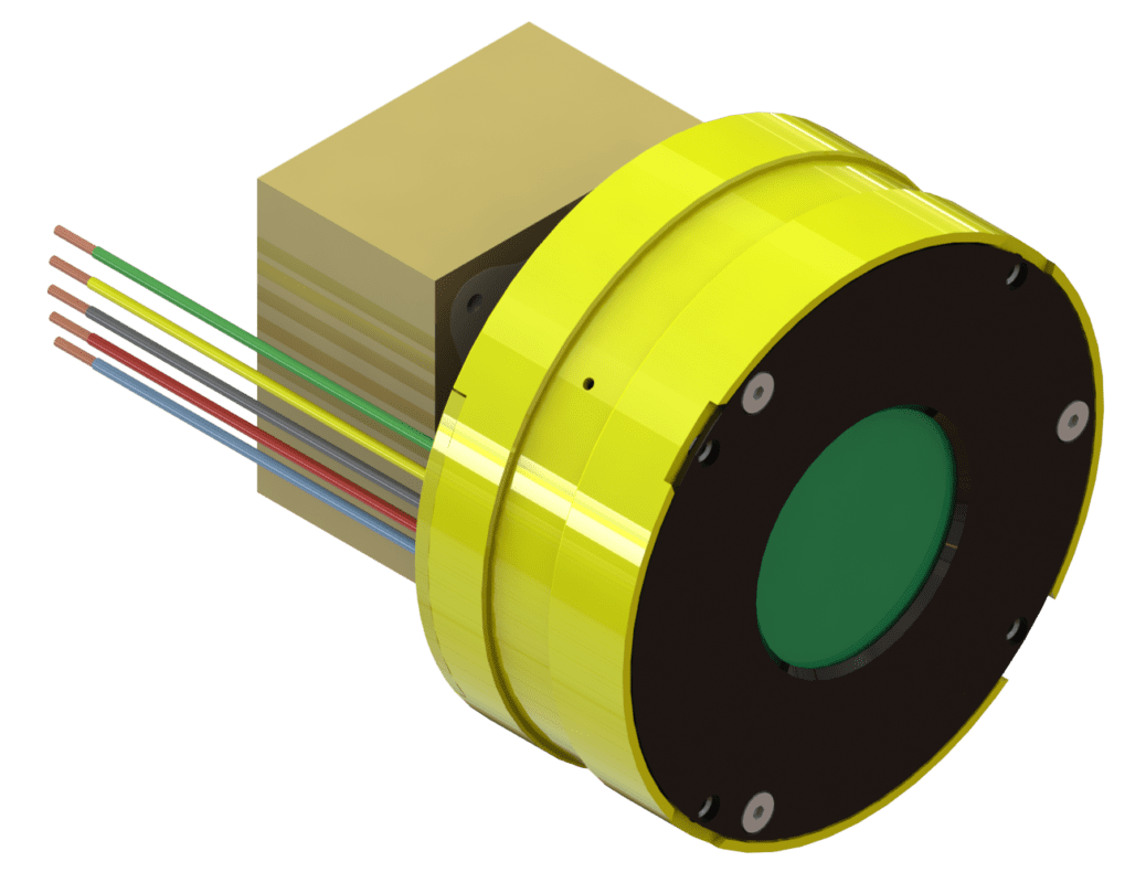
optical sensor mounting flexure lead designer


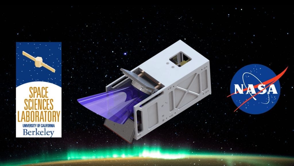
Berkeley Space Sciences Laboratory
This project was sponsored by Kodi Rider and Dr. Thomas Immel, with help from Cal Poly faculty advisor Dr. Eltahry Elghandour, and funding from NASA.


