The Illuminators
Cal Poly San Luis Obispo Mechanical Engineering Class of 2020

EMRAN BARYAL
Monterey, California
Design/Manufacturing Engineer
Budget Manager

Katherine Hui
Alhambra, California
Project Documentation & Technical Writer
Sponsor/Team Liaison

Emmett Lambert
Santa Maria, CALifornia
Information/Records Keeper
Concept Sketch Artist
Project Introduction Videos
Elevator Pitch
Technical Video
Acknowledgements
We would like to thank Dr. Javin Oza for being this project’s vision, direction, and greatest supporter. We would also like to thank our advisor, Sarah Harding, for her support and assistance in seeing our project through to the end. Finally, for providing the funds necessary to support this project and its embodiment of “Learn by Doing”, we would like to thank the Baker-Koob Endowment Committee.
PORTABLE FLUORESCENCE ILLUMINATOR
Problem Statement
Researchers in the field of molecular biology utilize ultraviolet (UV) illuminators to view the fluorescent output of UV-sensitive substances. However, current devices used to test fluorescence are expensive, not portable, difficult to use, and lack accessibility to the general public. The purpose of this project is to develop a portable and inexpensive ultraviolet illumination device capable of testing fluorescence in any research environment or classroom.
Design Constraints
- Within assembled dimensions of 7″ × 4.5″ × 1.5″
- Within unfolded dimensions of 15″ × 15″ × 1″
- Have a materials cost of $10 or less
- Weigh less than 5 pounds and can be carried in one hand
- Made of 85% recyclable materials
Illuminator Matchbox Design
A matchbox design was chosen for the following reasons:
- Allows for lighting and heating functions to be independent of one another
- Allows user to easily replace batteries, lights, and test tubes
- Easily disassembled and assembled even with multiple parts
- Simplicity in concept and intuitive with users
Other design choices to note:
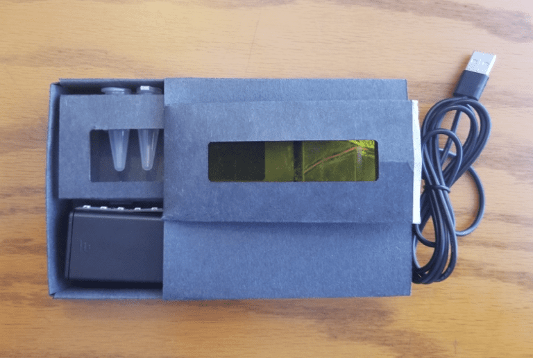
- All components (battery, LED lights, samples, heating element) are contained within the box or sheath
- Sheath, box, and test tube holders manufactured from recyclable paperboard
- Dual purpose test tube holders used to hold samples and as test tube stands
- USB heating element is placed opposite of light filter, independent of battery circuit used to power LED lights
- Yellow acrylic was chosen over amber (orange) for the light filter for better fluorescence viewing
- Blue 460-nanometer wavelength LED lights were used instead of UV LEDs because the wavelength was closer to the peak excitation wavelength of the samples
- Design is modular so two different sizes of test tube stands can be used, as well as different LED wavelengths.
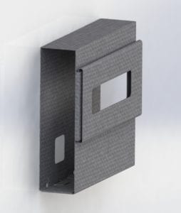
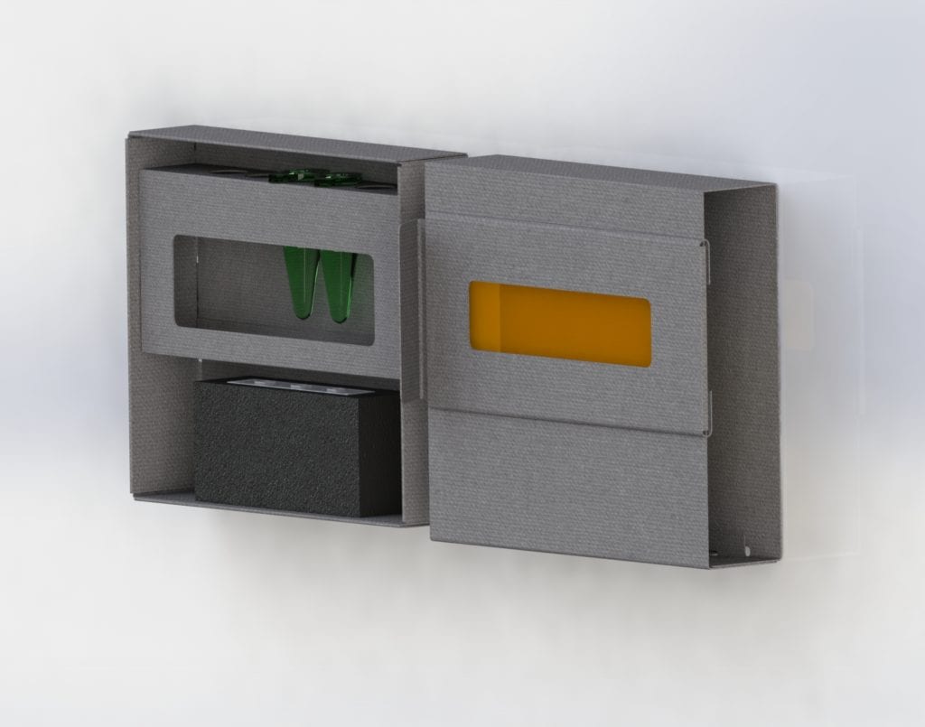
Matchbox concept allows the light filter and viewing window to slide over the samples, so the user can see the fluorescence.
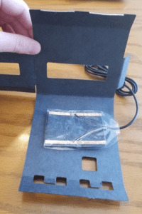
USB heater is placed on the back of the sheath, opposite the light filter.
Design Concept
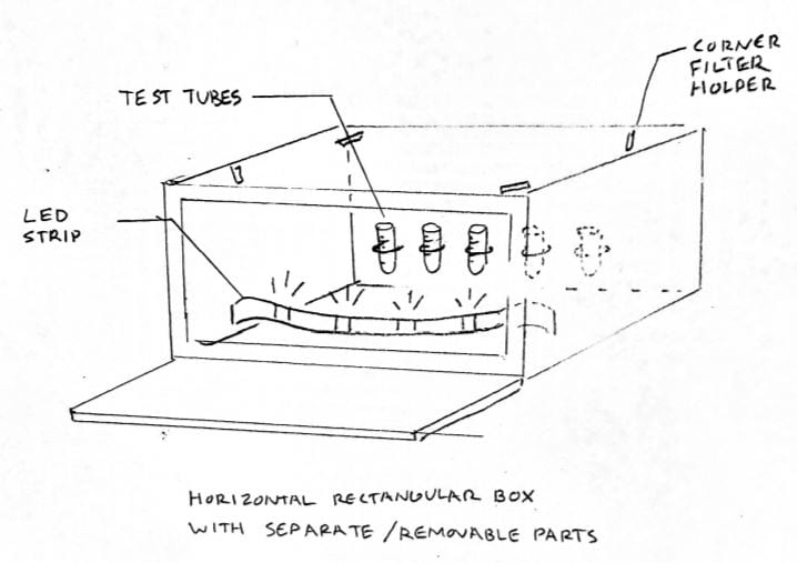

- (A) – Initial sketched concept design of a horizontal box device.
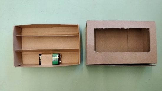
- (B) – Early matchbox prototype made from chipboard and kraft paper with lighting and test tube racks.
- (C) – Preliminary final box design with safety limit switches for UV LEDs and heating element underneath test tubes.
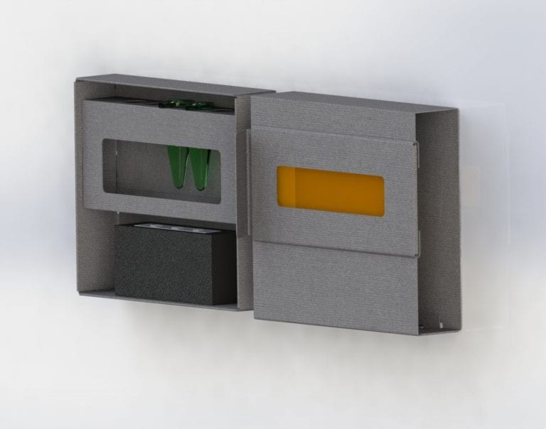
Rendered CAD model of final assembled illuminator, with sheath, box, test tube holder, and light filter.
This final CAD model allowed for dimensions of various components to be finalized; it also aided in creating the Cricut file to cut out the various components.
CAD DESIGN GALLERY

Cal Poly
This project is sponsored by Dr. Javin Oza,
Cal Poly Professor of Chemistry and Biochemistry.
Illuminator Manufacturing Process and Components
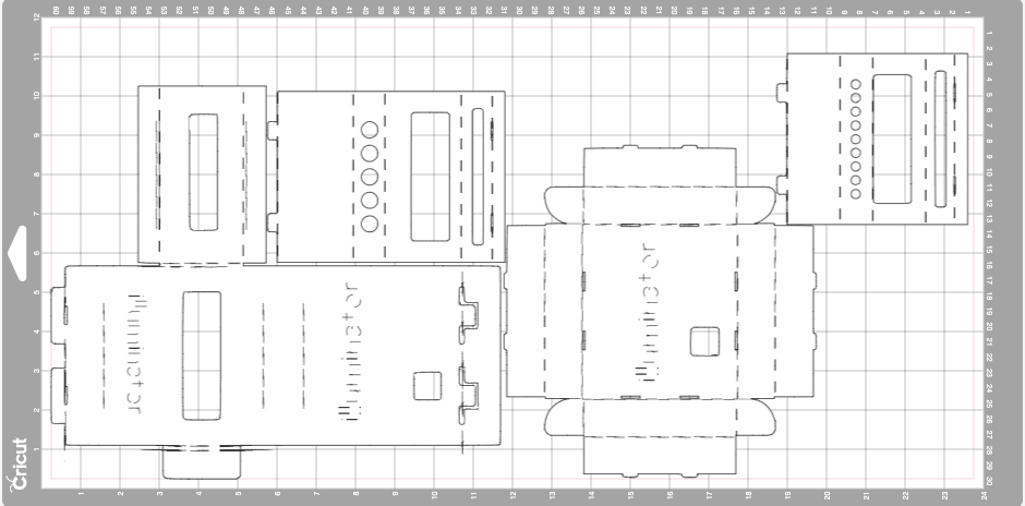
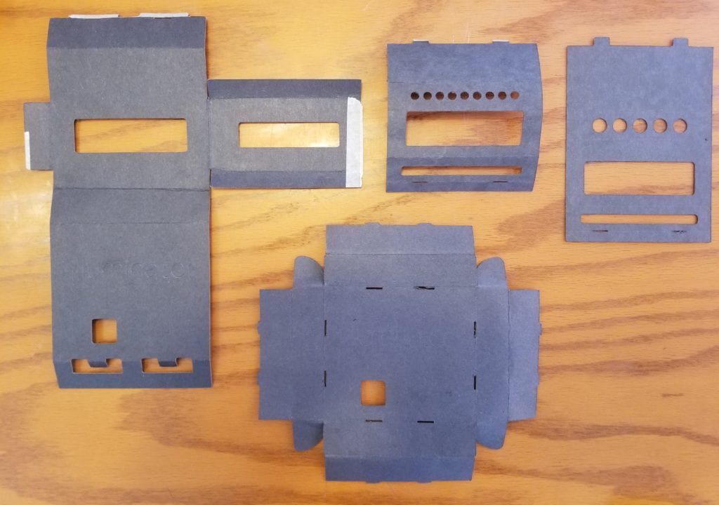
The flat pattern to be cut from the Cricut Machine fits on a 12″ × 24″ Cricut Mat. In one 15-minute run, the sheath, box, and both test tube holders are cut out, and the lines for folding are scored.
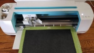
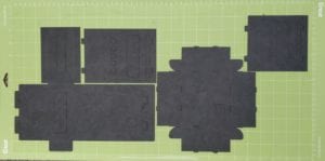
The Cricut uses the deep-cut blade and scoring wheel to make the cuts and folding lines for the illuminator pieces.
Design Verification
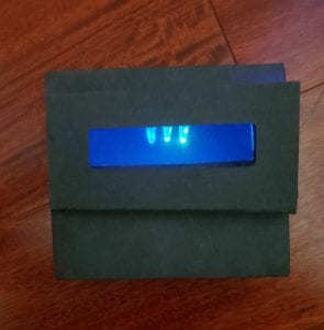
Lighting System – The 460-nanometer blue LED lights and yellow light filter were chosen because they provide the best green fluorescent output from the biological samples given. The image above shows that this combination can display not only the fluorescence, but the differences in fluorescence levels as well.
Heating System – The USB heating pad was tested in order to ensure that it could reach the necessary 30°-35° C for the chemical reactions in the proteins to speed up. The test revealed that the heater could reach 45° C , sufficient enough for the illuminator’s purposes.
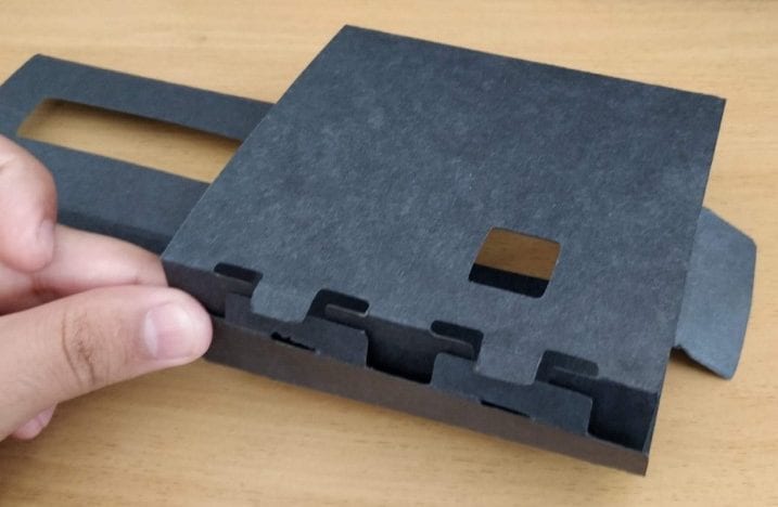
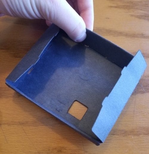
Images from the instructions manual showing how to insert the tabs of the sheath (left) and fold up the sides of the box (right). The assembly process for the illuminator is documented in an extensive manual detailing where to make the exact folds to form the sheath, box, and test tube holders, as well as assemble the electrical circuit.
Assembly Test- Our design was verified by testing the time needed to assemble the illuminator with Dr. Oza and eight of his lab students, using instructions we created. Most students were able to assemble the full illuminator (no electrical circuit) in 25 minutes. Some recommendations included pre-assembling the electrical circuit before giving the user a kit and creating further detail on some instructions.
Weight and Size Verification -The illuminator was weighed and measured to confirm that the device is portable and easy to handle for users. The weight was 0.6 lbs, well under the design constraint of 5 lbs. The assembled form of the illuminator has maximum dimensions of 4.55” X 4.12” X 1.14”, and flat dimensions of 11.35” X 9.85”. These dimensions are within the projected dimensions.
Final Design
Criteria
Under 5 lbs
Under $10
Recyclable Material
Dimensions – 7” X 4.5” X 1.5”
Specifications
Weight – 0.6 lbs ✓
Cost per Unit – $9.56 ✓
Materials – Paperboard, 4-ply ✓
Dimensions – 4.6” X 4.1” X 1.1” ✓
✓ – Specification met criteria
Custom Components
- Sheath
- Box
- Test Tube Holder, 0.6 mL
- Test Tube Holder, 2.0 mL
Stock Components
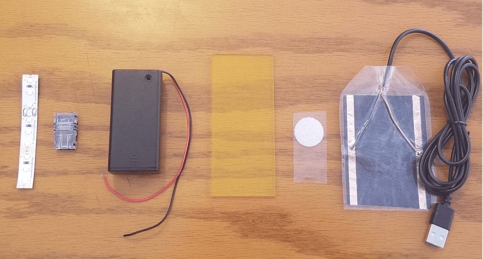
- Waveform Lighting 460 nm Blue LED lights
- 10 mm LED to wire connector
- 9-V battery holder
- AcrylandUSA yellow transparent acrylic
- 0.75″ diameter Velcro dots
- USB Heater
Future Application
The illuminator will be disseminated to the Cal Poly Chemistry and Biochemistry department and the Oza lab on campus. The illuminator will be used to facilitate classroom exercises in Cal Poly science labs and enhance the learning process for students. Furthermore, Dr. Oza and his lab will use the illuminator to assist their research in protein synthesis. Their work in the field of biological engineering and synthetic biology can be found here.
The illuminator also could have broader applications outside of Cal Poly. As an educational instrument, the device could be used in classrooms from the middle school to the university level as a science experiment. The device could also be used in field applications. It could be used in environmental testing to find dangerous chemicals in soil or water, or in medicine to indicate when a specific drug has finished being made (synthesized).
The illuminator is a much smaller, portable version of the benchtop device used in Dr. Oza’s lab, the BioTek Cytation 5. The portable illuminator provides a similar illumination function at a much lower price with less experience and technical knowledge necessary.
Recommendations
Improvements to be made if the illuminator were to be re-designed:
- Ensure the acrylic for the light filter is transparent and not translucent for the light to properly shine through and illuminate the samples
- Utilize 6-ply paperboard for sheath, box, and test tube holder components because it is thicker and more durable for the same cost as 4-ply paperboard. The Cricut is able to cut through this thickness of paperboard with the deep-point blade.
- Incorporate luminosity testing to empirically determine the correlation of sample fluorescence to sample amounts
- Test a larger number of subjects for device assembly to obtain a wider variety of age, experience, and opinion
- Utilize the Cricut machine at earlier stages of prototyping to make efficient use of time and focus on the iterations of the design
- Test the device with different colors of LED lights and filter colors in accordance with different types of protein samples and fluorescent reagents

