Introduction
The SAVER team is focused on creating an autonomous life saving device for marine environments. The project was initially focused on competing in NASA’s Micro-G NExT SAVER competition. Due to California state travel restrictions, the project was shifted to a university based project with the intention of providing an autonomous device that navigates to crew members who fall overboard on naval,private, and commercial vessels.
Our Team
Welcome to our senior project website. Here is a quick introduction to our team members to start off.

Ryan
Shields
Ryan is a 4th year Mechanical Engineer with a concentration in Mechatronics. Ryan is interested in robotics, controls, and process automation .

Max
Emerick
Max is a 5th-year mechanical engineering major concentrating in mechatronics. He enjoys surfing, mountain biking, and playing music in his free time. He will be starting his master’s at UCSB next year, studying dynamics and control.

Christopher Feickert
Christopher is a 5th year Mechanical Engineer with a concentration in Mechatronics and a double minor in Entrepreneurship and Mathematics. Christopher is interested in controls and design of automated systems.

Raymond
Impara
Ray is a 4th year Mechanical Engineer with a concentration in Mechatronics. Ray is interested in robotics and mechanical design.
Acknowledgements
Special thanks to our sponsor, Dr. John Ridgely, and our advisor, Dr. Peter Schuster, for their support and advice throughout this project.
Our Project Videos
Our Project's Digital Poster
Problem Statement
Create a method to assist a person at risk of drowning with a flotation device without requiring a member of a rescue team to deliver the flotation device directly, allowing search and rescue teams to assist that individual especially when line of sight is lost.
Design Constraints
- Minimum top speed of 5 mph.
- Maximum weight of 15 lbs.
- Minimum drop height of 20 ft.
- Maximum travel distance of 1 mile under battery power.
- Fully autonomous operation
Design Choices
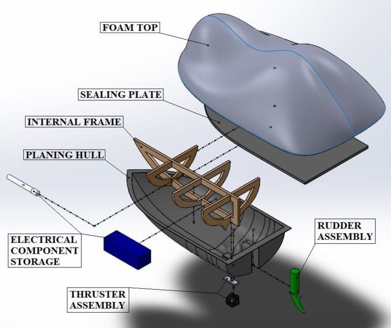
Planing hull chosen for two reasons:
- Reduces the amount of drag on the device.
- Allows for greater stability of the device in the ocean waves. This helps to prevent permanent capsizing.
Other design choices to note:
- Separable components to allow for easy maintenance.
- Internal waterproof chambers to prevent electronics damage in case of a leak.
- Choice of fiberglass hull with internal structural frame to reduce weight.
- Encased propulsion motor to prevent tangling and user injury.
- Top foam design to allow ease of use and prevent capsizing.
- Free RTOS implementation of code
Force Analysis
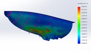
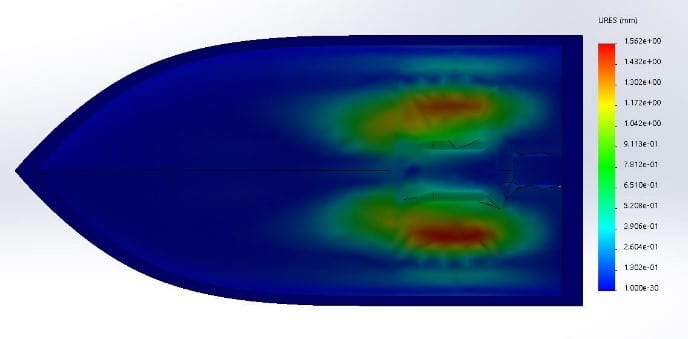
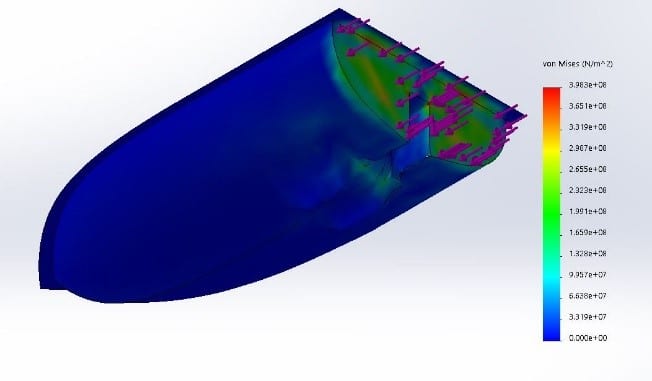
Using an energy analysis, combined with an impact force analysis, an expected impact force of 5.43 KN was calculated for the minimum drop height of 20 ft. FEA was completed on the hull to verify the structural integrity using this force. Future testing with an accelerometer was planned to verify the validity of the hand calculated force and the associated assumptions.
Using a force analysis combined with research into flotation devices, it was determined that the foam will need to apply 15 lbf of buoyancy to float a 250 lb person.
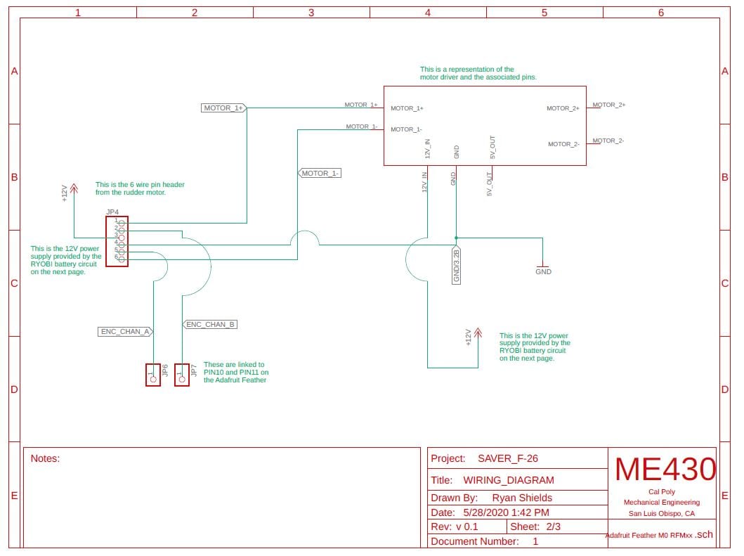
Electronics Design
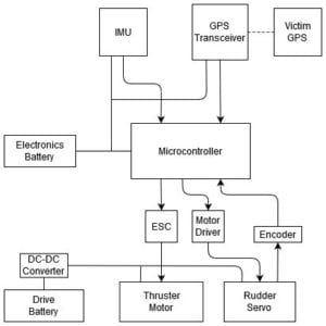
This diagram demonstrates how all of the electronics components are connected. Additionally, it demonstrates the flow of information through the use of arrows. Finally, the diagram depicts the necessary power sources for the project.
Code Design
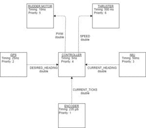
The code design for the SAVER device relies upon the use of finite state machines. In this picture, each square represents a task and each line communicates the manner in which information is relayed between the tasks. The general layout of the code involves all of the senors relaying their information to a controller task that calculates the angular velocity at which the rudder motor and drive motor should operate at.
Design Concept
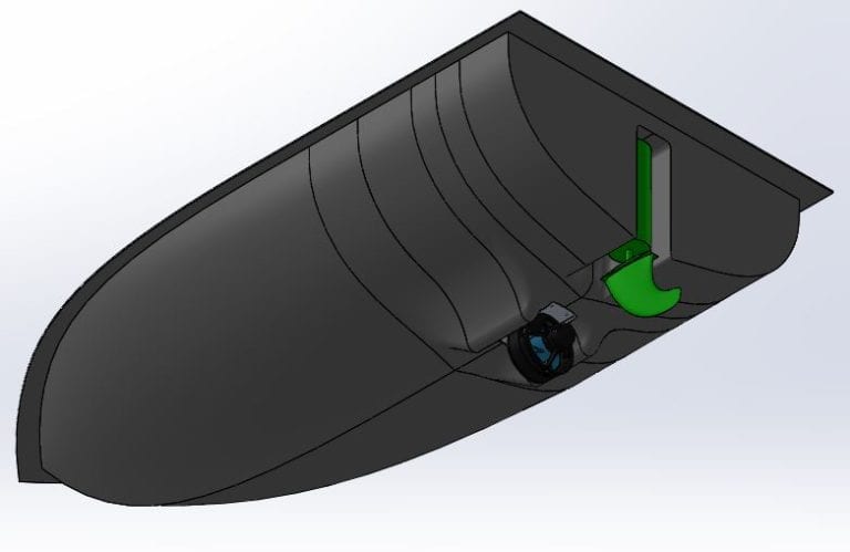
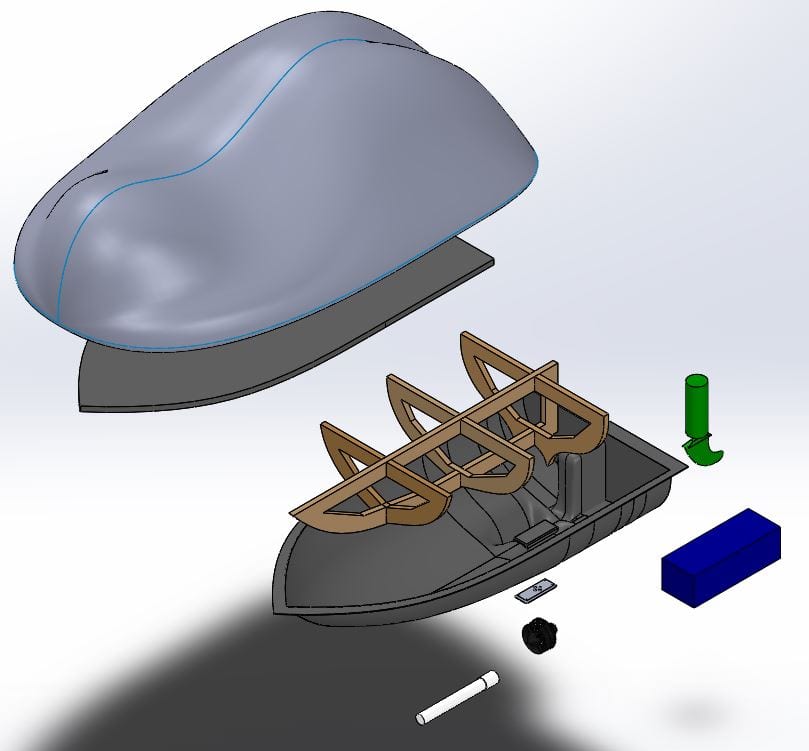
This CAD model allowed for design iteration and FEA. The device is approximately 4 feet long by 2 ft wide by 2 ft tall. Furthermore, the CAD permitted the creation of a scaled down 3-D model for testing stability.
GPS Analysis
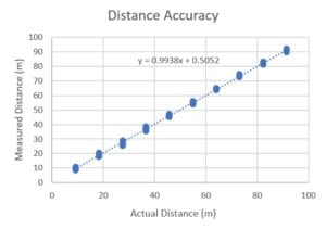
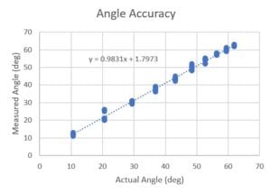
Detailed tests were run to determine the exact accuracy of the GPS system. The GPS system was taken to the Cal Poly football field and several data points were taken for angle and distance at each 10-yard line on each side of the field over three trials. As seen above, both the distance and angle measurements are sufficiently accurate for the purpose of SAVER. With 95% confidence, distance is estimated to be accurate to within 2 meters, and angle to within 3.3 degrees.
Actuator Selection
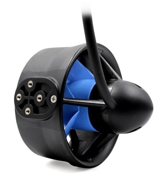
Through analysis, it was determined that a 425 Watt motor would be required to achieve the necessary speed of 5 mph with a planing hull. The T200 thruster from Blue Robotics was chosen as it provides 518 Watts at 18V and is completely waterproof. Additionally, the rudder motor was calculated to require 1.3 N*m of torque. The chosen 26 rpm planetary gear motor from Servocity provides 4.1 N*m of torque, providing a 3.15 factor of safety.
Design Verification
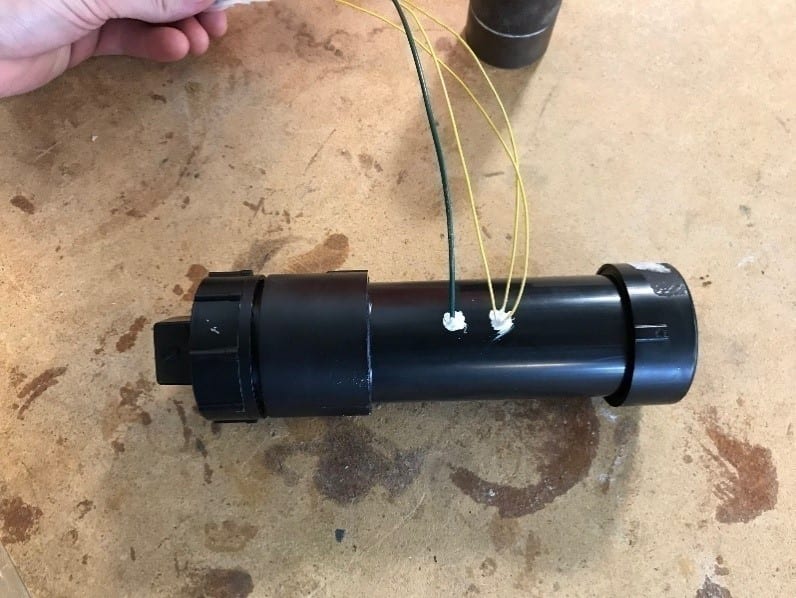
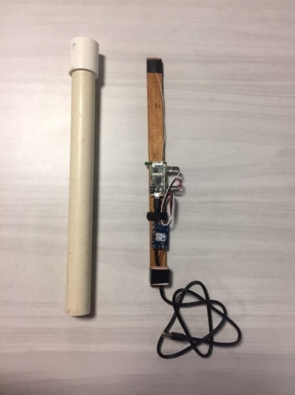
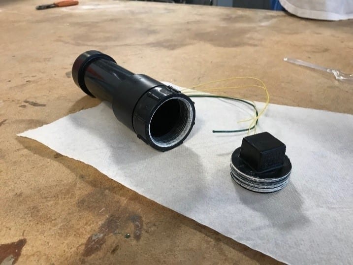
Waterproofing Test (Left): In order to waterproof the internal and external electrical components, 2 in. PVC pipes with removable caps were selected. Using thread sealer for the endcaps and PL Marine Loctite to fill holes where wires were drilled through the side, the PVC tubes were closed with a paper towel inside. After submerging the tubes for an hour, no water had leaked into the tubes.
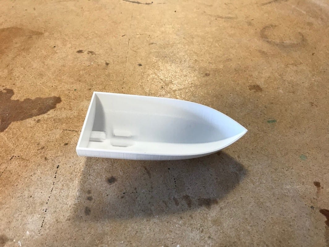
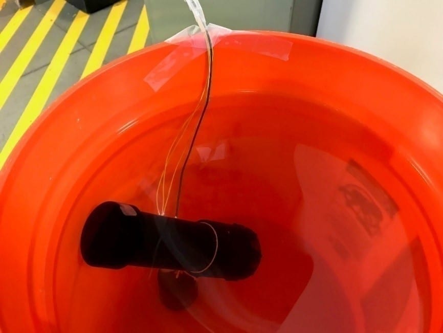
Stability Test (Right): The turning stability and orientational stability of the device are important to ensure the device reaches the victim. The testing device was made from a 3-D printed hull, weights added in the bottom of the hull to simulate the weight of the internal components, and spray foam formed into the approximate shape of our desired foam top. The device was placed in a bucket of water in multiple orientations to ensure that the device always righted itself. Additionally, waves were simulated while the boat was moving to depict that the boat would maintain its course through waves.
Change of Scope
Due to the change in Cal Poly’s spring quarter to an online environment without lab access, the scope of the project was changed.
- Physical build was not feasible without shop access
- Outsourcing physical build not fiscally feasible
Accordingly, the project was shifted to focus on the mechatronics portion of the device.
- Final prototype composed of code to run autonomous navigation
- Documentation shifted to focus on mechatronics and plans for a future team to complete physical body building and testing
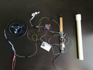
Mechatronics Assembly
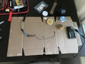
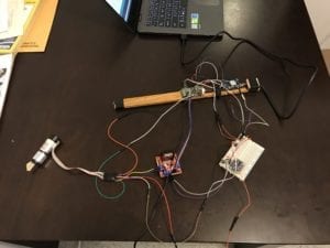
Each team member was assigned a component to get working. The IMU, rudder motor/encoder, thruster, and GPS/controller were all built and programmed independently by individual team members. This allowed the team to avoid remote debugging for as much of the project as possible. After all components were working independently, they were all shipped to San Luis Obispo, where one team member took responsibility for the physical integration of the components. After the mechatronics system was put together, brief testing was completed to ensure that all components were connected correctly and that the software worked as expected.
Final Mechatronics Design
Code Implementations
- Open Loop Velocity Controller
- Closed Loop Rudder Positional Controller
- PWM control of Rudder Motor
- Quadrature Encoder
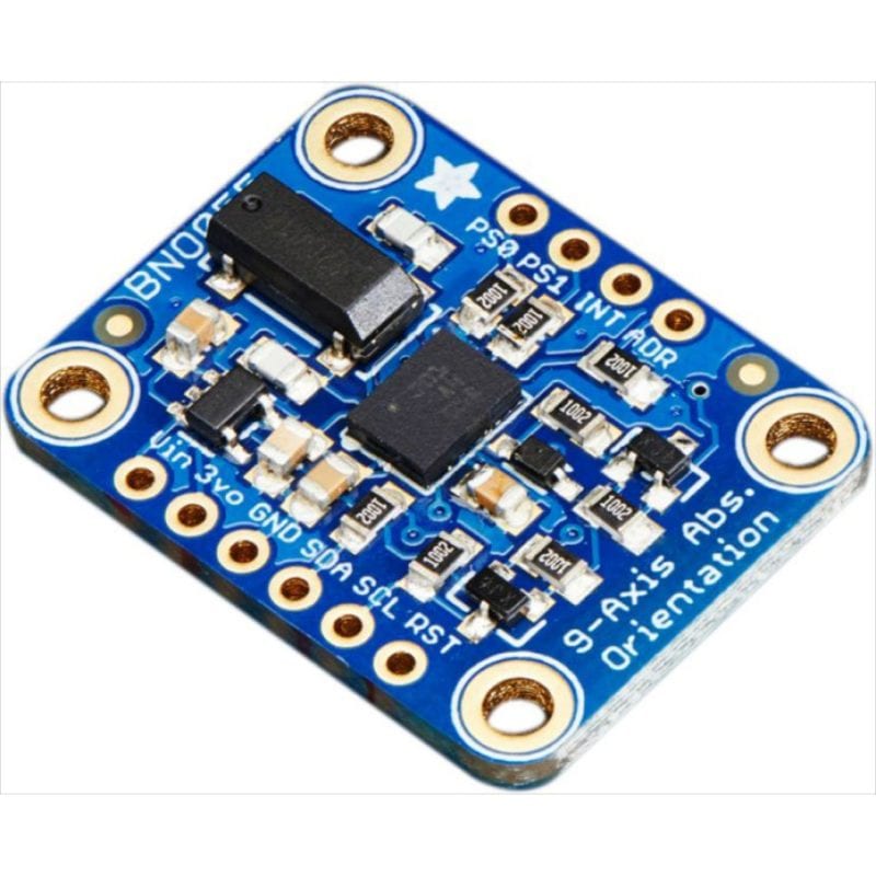
- BNO055 IMU Reader
- RTOS implementations of GPS, Navigation task, and LoRa Radio (Sponsor provided)
Mechatronics Components
- T200 Thruster from Blue Robotics
- 26 RPS Planetary Gear Motor w/ Encoder
- Qunqi L298N Motor Driver Breakout Board
- Feather M0 RFM96 LoRa Boards (Sponsor provided)
- BNO055 IMU Breakout Board
Future Application
The SAVER device will have varied uses once the full device can be constructed and tested. Upon completion, the Coast Guard has stated that they would be interested in the device to assist with SAR of individuals who fall overboard at sea. Additionally, large freighters and cruise ships can use the device to assist employees and passengers who fall overboard. Finally, future implementations of the device would include a launching device and a method for using a controls systems to allow multiple devices to work in unison to rescue multiple crew overboard.
Recommendations
Improvements to be made if device were to be re-designed:
- Add rings to top foam to allow for people to more easily hold on
- Create a carbon fiber hull and test it to optimize drag
- Create a method to charge the batteries while the device is fully assembled.
- Reduce the number of bolts on the sealing plate for easier assembly
- Utilize a better water resistant material than MDF for the frame.
Definitions
- RTOS- Real Time Operating System; a method of programming that makes cooperative multitasking easy
- Planing hull- a hull shape that allows a craft to skim on the surface of the water rather than cutting through it
- IMU- Inertial Measurement Unit; measures absolute orientation of the device
- FEA- Finite Element Analysis; a modeling method of analyzing the stress on the structure
- Encoder- Device on a motor that allows for measuring angular or linear position
- SAR- Search and Rescue