Our Team
I am text block. Click edit button to change.

Michael Petralia
Team Lead
Hi, my name is Michael Petralia and I’m a fourth year student who enjoys playing volleyball and being outdoors!

Foster Sutton
Power Subsystem Designer
My name is Foster, I’m a fifth year engineering student and I love exploring the central coast beaches and breweries!

Eldar Rastoder
Steering Subsystem Designer
I’m Eldar Rastoder and I’m a mechanical engineering student from Sunnyvale, CA. Some of my hobbies are soccer, running, and video gaming.

Jeff Neumann
Support and Braking Designer
I am Jeff, I am from Paso Robles, and I really enjoy traveling to the great wineries in San Luis Obispo County.
Acknowledgements
We would like to take a chance to thank California Children’s Services for the opportunity to make a difference with this project. We would also like to thank the Baker-Koob Foundation and Cal Poly ME-SFAC for their financial contributions to this project, as well as our Senior Project Advisor, Sarah Harding, for her assistance and guidance throughout this project; without them, none of this would be possible.
Our Project Videos
adaptive tricycle Digital Poster
Problem Statement
The purpose of the project is to design and manufacture an adaptive vehicle, for the SLO High student, that serves as a form of exercise and can be easily operated by them with no outside assistance, all while remaining comfortable and intuitive for the student to operate.
Design Constraints
- The user of this tricycle does not have use of their arms nor their legs.
- There is a minimal amount of input force available from the user.
- The initial trike to be adapted has dimension and support constraints.
Design Verification
There were a handful of specifications we kept in mind when ideating the adaptive tricycle; the specifications mentioned are as follows: top speed under the student’s own control, ease of use, seat design, steering performance, time to access the seat, braking distance, weight, dimensions, aesthetics, time until top speed. These specifications account for both the needs and wants of the student, as they are the primary and/or sole user of the tricycle. Each test, whether it is measuring the time until the top speed, time to access, or braking distance, all are imperative in regards to determining the usability of the tricycle. We aimed to qualify all of the specifications and kept them in mind as we designed and manufactured the trike.
Power Subsystem
The Crank Arm – Power Bar Assembly was chosen for the following reasons:
- With limited range of motion, a direct translation of input force is optimal.
- The Crank Arm allows for a larger input of Torque to drive the tricycle.
- The power bar allows the user to use their torso to drive the tricycle, as opposed to their arms.
Other design choices to note:
- The Crank Arms are connected to smaller crank sprockets that are chained to the main drive sprocket, which are connected to the wheels. This gear ratio allows for a smaller input force needed to drive the tricycle.
- Material choices were made for the powering subsystem based on material deflection and weight of the material.
- Since we chose not to weld, but rather fasten these components, we chose Aluminum 6061 as the material for the Power Bar and Crank Arms.
- Stress and deflection analysis was the primary method for determining the sizing of these components, leading us to choose a 1/4-in plate for the power bar, and a 2-in diameter hollow tube with a 1/4-in wall thickness.
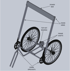
This is the CAD model displaying the overall layout of the Power Subsystem for the tricycle. This picture locates all necessary features for the subsystem, showing the power bar and crank arm features, how they are connected, and how they are connected to the tricycle. This also displays the support frame of the existing tricycle.

This project is sponsored by the Baker Koob Endowment and the Cal Poly Mechanical Engineering Student Fee Allocation Committee (ME-SFAC)
Steering Subsystem

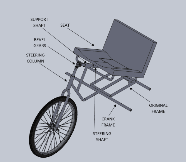
This is the CAD model displaying the overall layout of the Steering Subsystem for the tricycle. This picture locates all necessary features for the subsystem, showing the support and steering shafts, the steering column, and the bevel gears that connect them together to translate motion. (The seat clamping mechanism was planned to be implemented later on in the design process).
- The Bevel Gear Steering – Seat Design Assembly was chosen for the following reasons:
- The bevel gears connecting the steering column to the steering shaft were the most efficient method of translating rotational motion.
- The 1:1 ratio for bevel gears allowed for a comfortable leaning angle to initiate the steering.
- Located inside of the steering shaft is the support shaft, that delivered support and connection for the seat and the original trike frame.
- For further support, a seat clamp was to be installed under the seat, also attaching the seat to the trike frame.
- The steering column and steering shaft must be at a 90 degree interface, and the original steering column was at about a 30 degree tilt from vertical. This created a need for the steering shaft and seat to be tilted that same angle up from horizontal, to guarantee that interface
Braking Subsystem
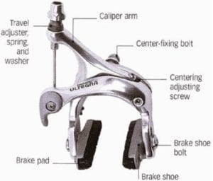
The picture above shows how the caliper breaking mechanism works on a local level.
Caliper Braking Assembly was chosen for the following reasons:
- After an attempt at implementing a coaster braking mechanism on the tricycle, we realized there was such limited range of motion, that a coaster brake would not suffice.
- The caliper braking method only needs a single pushing or pulling input force to be activated, making it the ideal choice for the tricycle.
Other design choices to note:
- The method of force implementation comes from the user leaning back, pulling a strap connected to the crank arm, allowing the braking mechanism to engage.
- The strap that assists in engaging the braking input force also acts as a method of support for the user, keeping their torso inside the vehicle at all times.
Manufacturing Process and Components
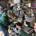
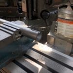
In the pictures shown above, we were able to make some important initial modifications to the crank arm (right picture) and the power bar (not pictured). Due to unforeseen circumstances, only preliminary manufacturing processes were completed. Also, given these circumstances, the tricycle was not altered or modified in any way. This lack of tricycle modification allows further groups to make other decisions regarding the tricycle, if necessary.
Final Design
As previously mentioned, we were unable to finish manufacturing and implementing our designs. With that, though, comes the processes, methods, and materials we planned on using when implementing the subsystems. Below are lists of the stock and custom components that were vital to the manufacturing and implementation of these subsystems.
Custom Components
- Steering mechanism
- Power bar powering system
- Steel body and frame work
Stock Components
- Chains
- Drive sprockets
- Free sprockets
- Bevel gears
- Bearings
- Caliper brake
Future Application
The initial tricycle given to our group had absolutely no modifications made on it. This allows future senior project groups to have the opportunity to take on this task and make those modifications and implement their designs through manufacturing, all with our design verification and planning readily available to them.
With that, there is room for this idea to be adapted to other tricycles as well. Our team’s design is unique and specified to one user, but with minor adjustments, this design has the foundation to be taken and modified to become a more general design, that can allow those without use of their arms or legs operate a tricycle for exercise.
Recommendations
This document serves as a contract between our team and the sponsor over the end goals of this project. The information collected through research has led to an in-depth ideation process and later development of many design possibilities, of which have been narrowed down to one finalized design. The next step in the process was to begin assembling our verification prototype and test it against our specifications before assembling our final design, but due to unforeseen circumstances, manufacturing and testing of the final design prototype was unable to be completed.
Instead, we aim to assist any who wish to adapt their own tricycle in order to serve a similar purpose to that of ours. We went through many rounds of ideation that consisted of what we believed to be great methods of operation of completion for the tricycle, but we had realized that these methods were not achievable. Of these things were the implementation of the coaster brake; due to limited motion of the tricycle, a coaster brake would have been impossible to implement. With that, our group realized that manufacturing takes a great deal more time than anticipated, leading to a shortened timeline of operation for the completion of the design. These recommendations can lead to a more efficient design.