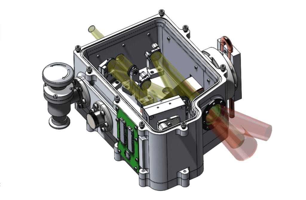
About SIGHT
Caltech and the Cal Poly SIGHT senior project team have worked together during the 2019-2020 school year to develop an important system that will drastically improve the capabilities of the Hale Telescope at Palomar Observatory in San Diego. It is called Sharpening Images using Guidestars at the Hale Telescope, or SIGHT. This system uses adaptive optics to help scientists at Palomar’s 200-inch telescope observe astronomical events with unprecedented clarity.
When pointing a telescope on the ground towards an object in space, the image is blurred due to disturbances the light experiences as it travels through Earth’s atmosphere, such as temperature and pressure differences. Adaptive optics uses a laser that is pointed directly where the telescope is pointing to detect exactly how the light is being distorted. The telescope collects the light and corrects it using a deformable mirror. This is a mirror that can change the shape of its surface using thousands of actuators and will correct the wavefront errors.
Our Team

Josh Robinson
Pressure Vessel & Radiation Shielding Lead
After graduating, I will be working full-time as a systems engineer for Northrop Grumman in Redondo Beach, while pursuing a masters in photonics at UCLA. When the pandemic is over, I will be hiking the Inca trail to Machu Picchu.
Jordan Rupp
Bipods, Baseplate, & DM Mount Lead
After graduation I plan to celebrate for a week camping in Zion National Park. In July I am going to Florida to watch the Mars Rover “Perseverance” launch from Cape Canaveral. I will then begin working at JPL at the end of July as an optomechanical engineer.

Jonah Silva
Cooling System Lead
After graduating, I will continue to search for a full-time engineering position in SLO county. Over the summer, I will also spend ample time surfing, volunteering as the High School Youth Leader at Calvary SLO, and hanging out with my wife.

Samantha Tran
Optic mounts Lead
After graduation I plan on road tripping to Seattle, Washington, where I will intern for the mechanical engineering team at Modern Electron. In the fall I will go back to San Luis Obispo to begin the Masters Program at Cal Poly.
Acknowledgements
We would like to express our deep gratitude to our sponsors, Michael Feeney and Dr. Richard Dekany, for their continual support, patient guidance, and useful critiques throughout our project. We would also like to thank Professor Peter Schuster for his advice and assistance in keeping our progress on schedule, and for also guiding us through the design-build-test engineering project life cycle.
Our deep appreciation is also extended to Caltech for funding our prototyping and testing.
Our Project Videos
Our Project's Digital Poster
Problem Statement
The SIGHT team needs a way to support/constrain the optical components of the Science Cryostat within the existing structure of the telescope, while maintaining the components in a cooled, vacuum-sealed environment.
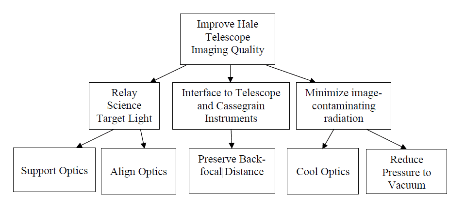
Functional Decomposition Diagram for the SIGHT Science Cryostat.
Subsystem Breakdown
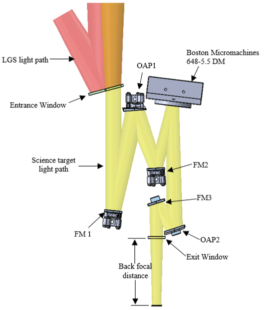
Optics: must have the necessary tip/tilt and translational adjustability for each mirror type.
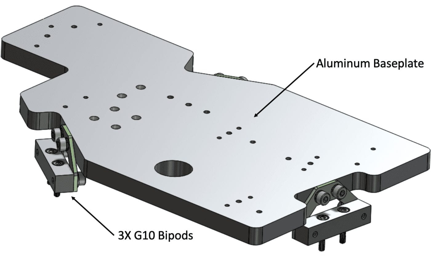
Baseplate: must hold optic mounts in place and must be thermally isolated from the pressure vessel.
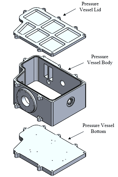
Pressure Vessel: must hold a vacuum for one month and provide all the necessary interfaces for the Science Cryostat to interface with the rest of the SIGHT instruments.
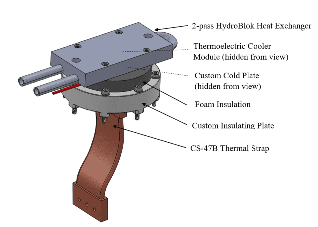
Cooling System: must cool the optics and baseplate to -30 °C without significantly cooling the pressure vessel and causing condensation on the entrance and exit windows.
Concept Design
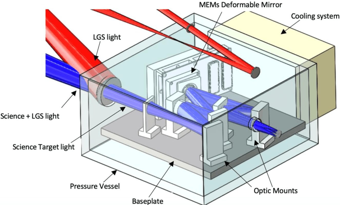
The purpose of the conceptual design was to understand the geometric constraints of the Science Cryostat and determine a basic layout of our design.
PDR Design
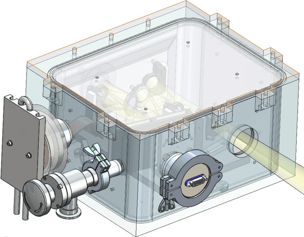
The PDR design incorporated all the necessary components, but needed to be further analyzed and optimized.
Design Decisions
Optic Mounts:
- Custom fixed mount for FM 3 and OAP 2 due to packaging constraints
- Custom DM base to connect the OTS DM mount to the baseplate
Baseplate:
- Custom baseplate allows custom placement of mounting holes for the optic mounts
- G10 bipods to thermally isolate the baseplate from the pressure vessel while providing enough stiffness to minimize deflection of the baseplate
- The top and bottom lids will be removable to make manufacturing and assembly easier
- Contour the shape as close to the optic components as possible
- Lightweight where possible
Cooling System:
- Radiation shielding in between the pressure vessel and baseplate to reduce heat load
- Custom cooling system because there are no stock systems that meet our design requirements
- Thermoelectric cooler is the main cooling component
Analysis
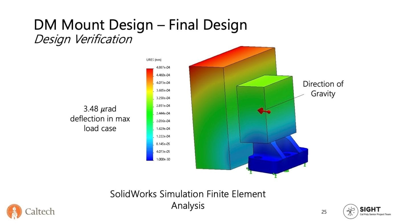
The maximum deflection case of the DM assembly occurs with the gravitational force normal to the mirror surface. This resulted in a maximum deflection of 0.5 microns at the top of the DM assembly.
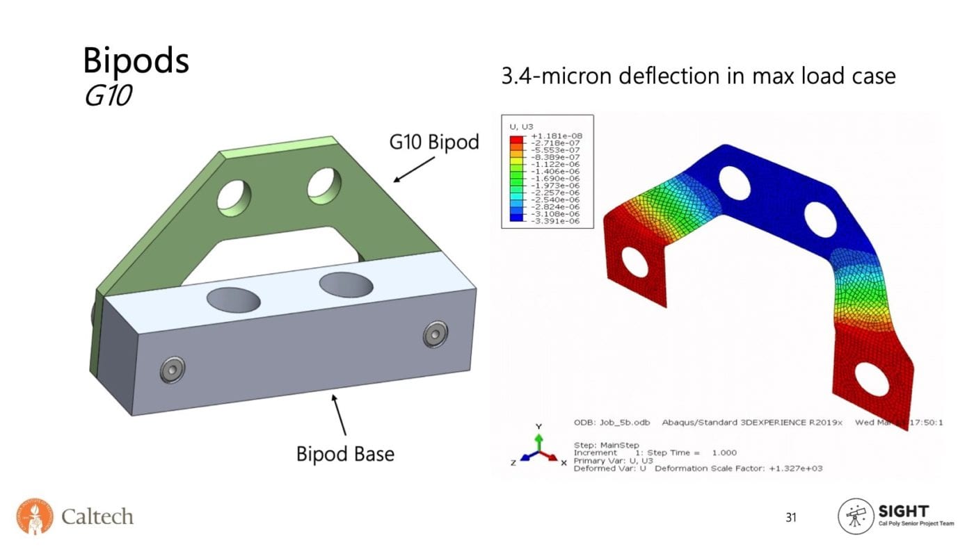
Using stock G10 sheet thickness, the optimum sheet thickness of 2.032 mm was determined. In the maximum deflection case, one bipod carried half the baseplate’s weight. This resulted in a maximum displacement of 3.4 microns.
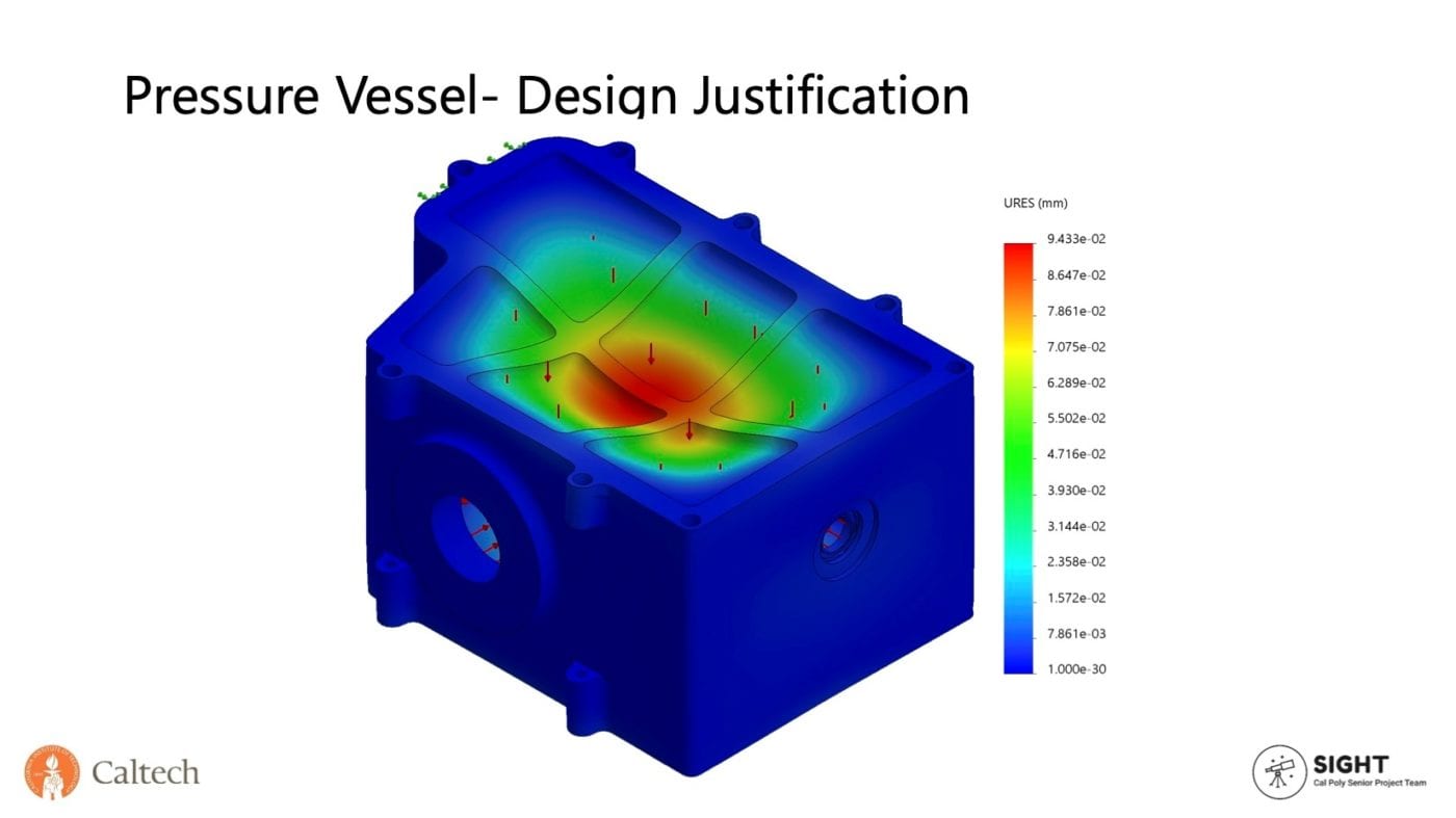
A pressure difference of 13.35 psi was applied normal to each inner wall to simulate a vacuum pressure of 1.5 psi for the maximum deflection and maximum stress cases. The maximum deflection occurs at the unsupported top and bottom and is 94 microns. The maximum stress occurs on the pressure vessel lid and has a factor of safety of 2.5.
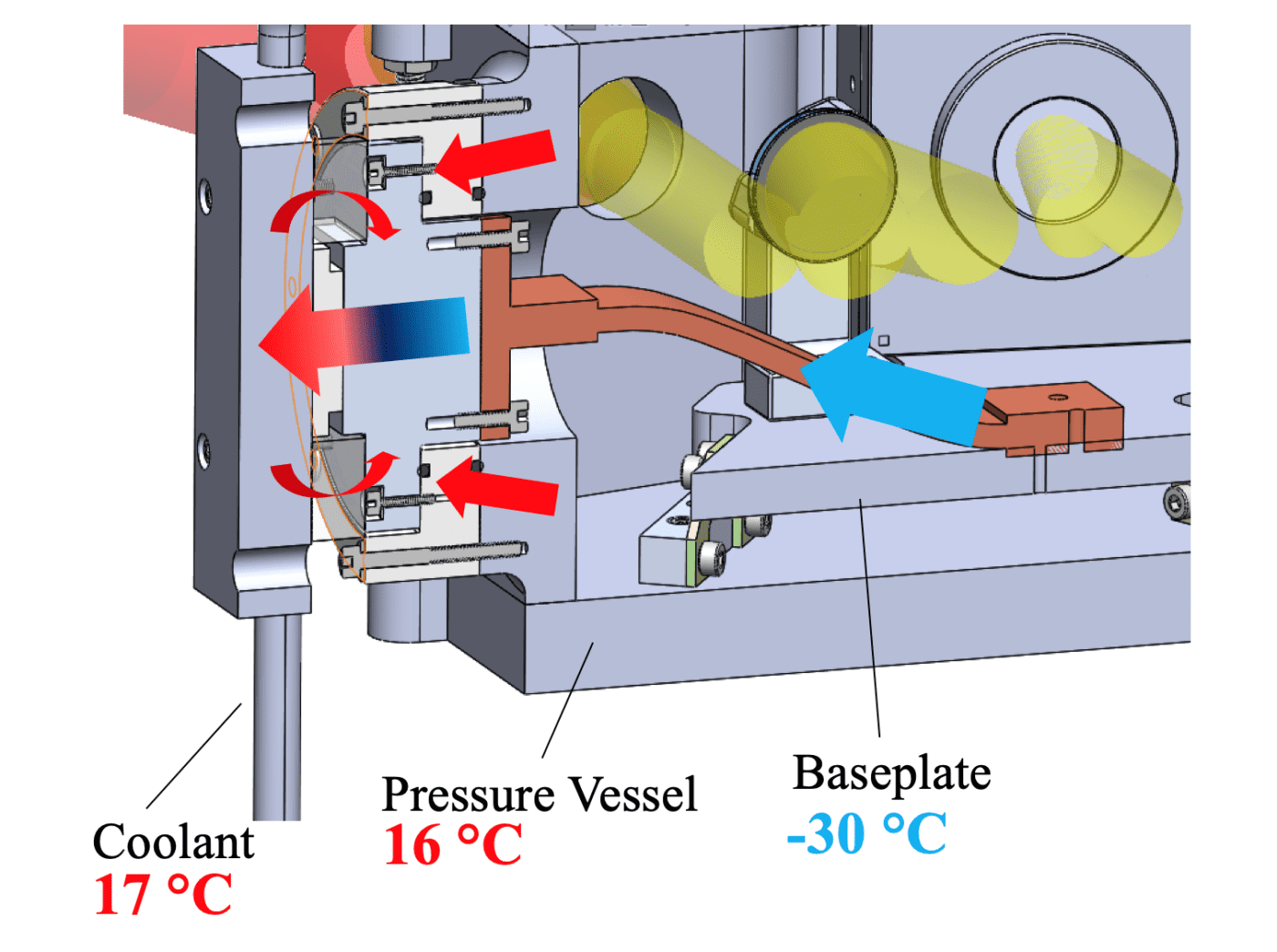
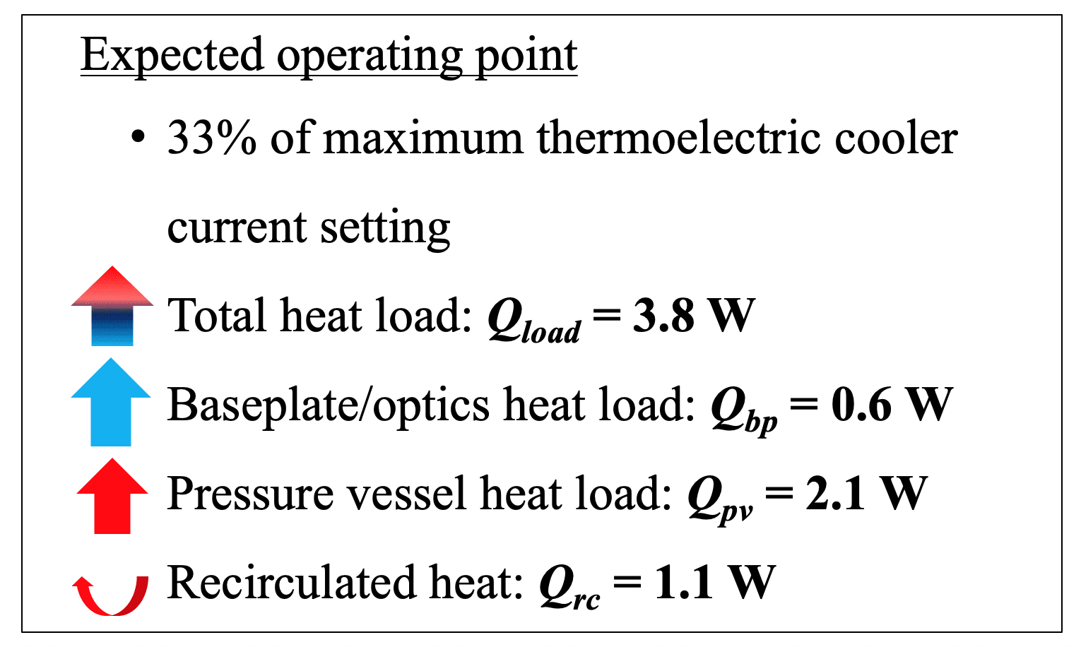
A multi-mode heat transfer analysis was performed using EES. This simulation was used to iterate the materials and layer thicknesses surrounding the thermoelectric cooler. The results verify that the final design can cool the baseplate to -30 °C while operating at only 33% of its maximum current setting.
Manufacturing Process
For the verification prototype, the optics mounts, baseplate, and bipods were machined on a CNC mill by our sponsor Michael Feeney. The final product will also be manufactured with a CNC.
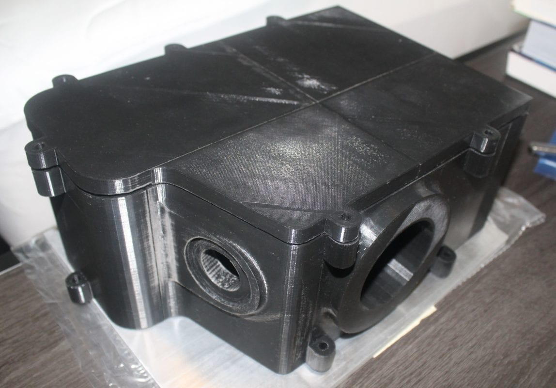
For the verification prototype, the pressure vessel was 3D-printed. For the final product, the pressure vessel will be machined on a 5-axis CNC mill.

This project is sponsored by Caltech
with technical guidance from Michael Feeney
and Dr. Richard Dekany
Final Design
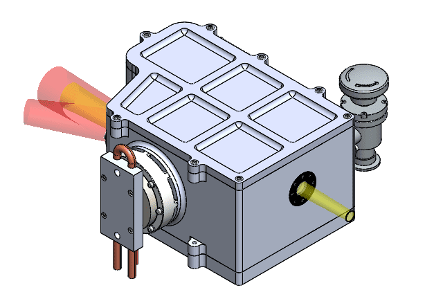
Specifications
Weight: 10.88 kg
System Dimensions: (360 x 310 x 160) mm
Total Cost: $12,100
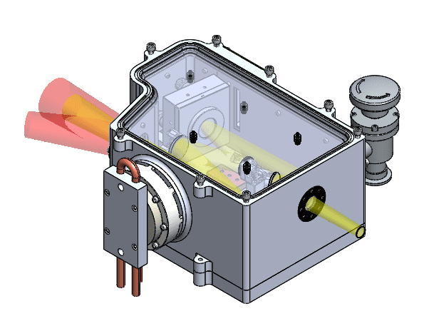
Custom Components
- 6061 aluminum mount bases
- 6061 aluminum fixed mirror mount
- 6061 aluminum OAP mount
- 6061 aluminum DM mount base
- G10 bipods
- 6061 aluminum baseplate
- 6061 aluminum pressure vessel
- Polished aluminum radiation shielding
- Cold plate
- Foam insulation
- Insulating plate
Stock Components
- Newport kinematic mirror mounts
- Thorlabs deformable mirror mount
- Thermoelectric cooler module
- CS-47B thermal strap
- 2-pass HydroBlock heat exchanger (with post machining
Design Verification
Visual Inspection & Basic Functionality Test
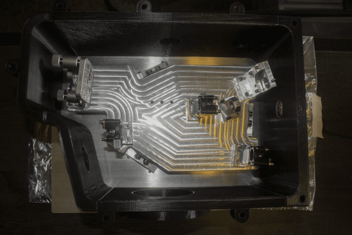
We assembled the optic mounts, bipods, baseplate, and pressure vessel as designed by CDR to verify the packaging requirements could be met by visual inspection. Additionally, basic functionality tests were performed on the optic mounts to ensure they could be adjusted.
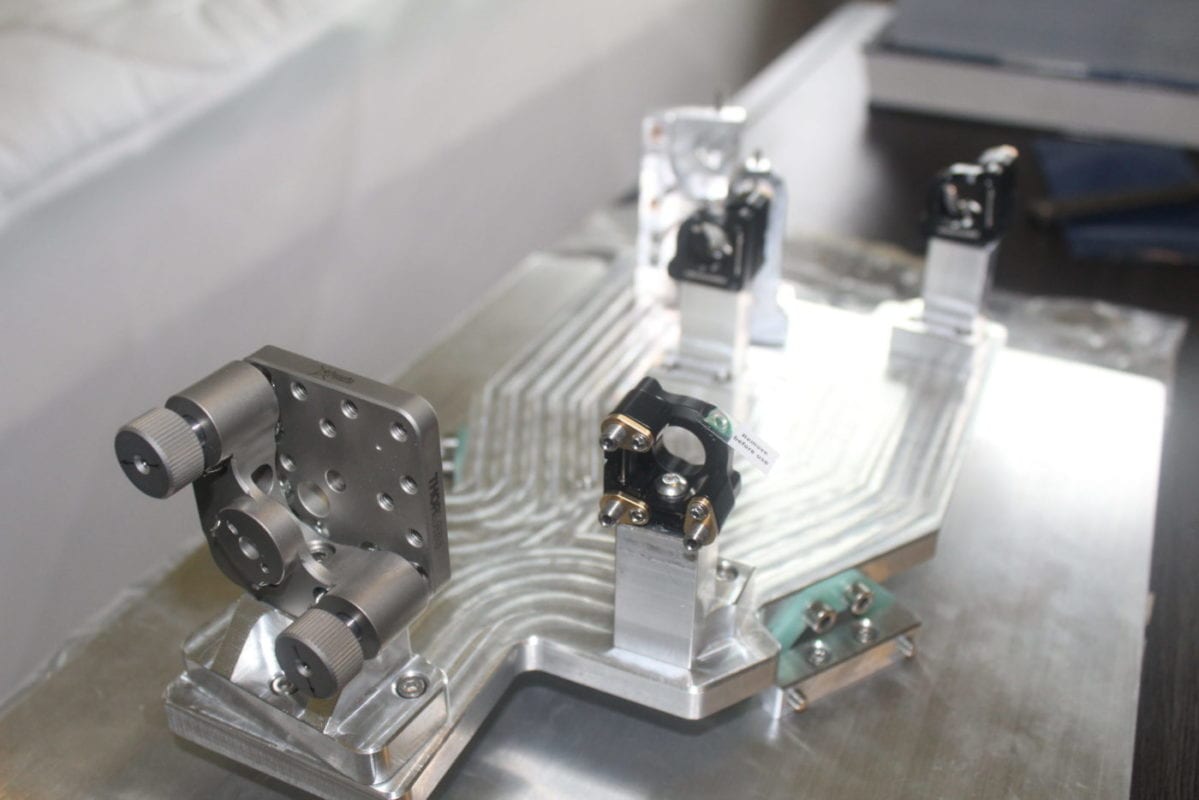
Future Application
Our verification prototype is the first iteration of the Science Cryostat that will be integrated into the Hale Telescope in 2023. Caltech plans on testing our design, doing further prototyping, and making potential design changes before its implementation.
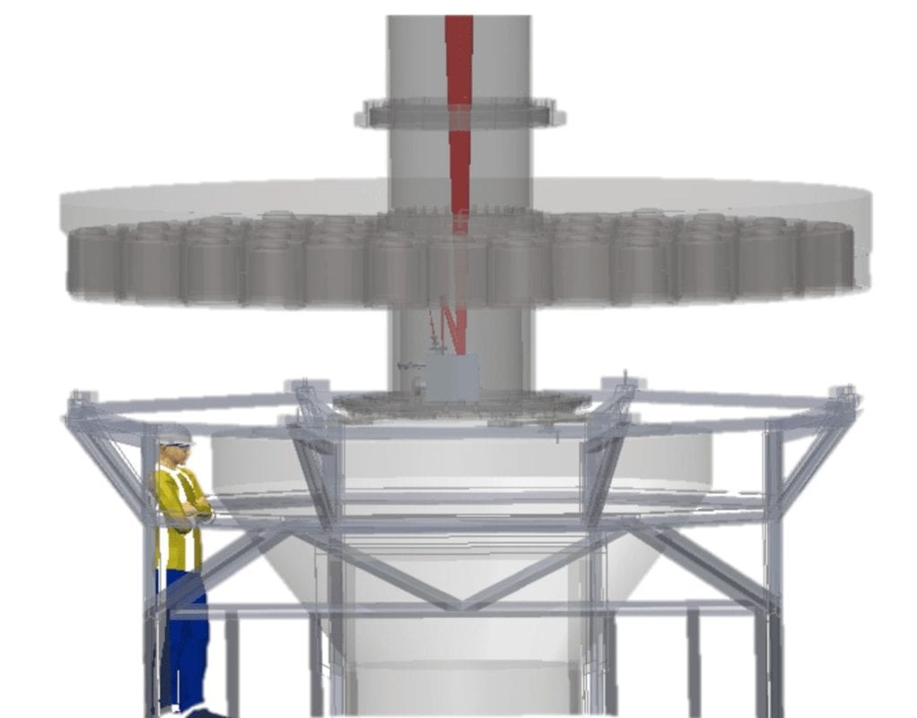
Recommendations
Further Testing Suggestions:
- Optical Mount Adjustability Test: verify the adjustability of the custom OAP 2 mount meets the desired tolerances
- Pressure Vessel Vacuum Test: draw a vacuum on the assembled pressure vessel and verify its maximum deflection and stress are within its design specifications
- Cooling System Capacity Test: run the cooling system detached from the pressure vessel and characterize its performance
- Science Cryostat Cooling Test: verify that the baseplate and optical components cool down to -30 °C without condensation occurring on the entrance and exit windows
Improvements to be made for future iterations of the Science Cryostat:
- Dry air should be gently blown across the pressure vessel to further prevent condensation on the entrance and exit windows
- O-rings will need to be re-sized if component dimensions change
- The vacuum interface board needs to be designed since this component is outside our project’s scope of work

