Our Team
The Weekend Whippers.

Kaitlin DeHerrera
Project manager
I’ve been climbing for several years and have loved the outdoors for as long as I can remember. I was happy to have an excuse to sneak rock climbing into my engineering studies. My favorite part of the process was ideation, rapid prototyping, creative design, and learning about design for manufacturing in a niche industry.

John Hickey
Manufacturing Lead
As an avid rock climber, I took the opportunity to propose this project so that I could combine my passions with my future career aspirations. This project has had a profound impact on me and has helped me land my dream job in the outdoor industry. I enjoy the design, build, and test methods and look forward to using it frequently in the future.

Jared Christner
Team Treasurer
Although I’m not as much of a passionate rock climber as my teammates, I really enjoyed learning more about rock climbing industry. My favorite part of the project was building prototypes to test out new ideas and creating the FEA model of the cam’s lobes

Ryan Edwards
Support Engineer
As a rock climber I was very excited when I could apply my engineering skills to a project that I am passionate about. It has been a pleasure working on this project and strengthening my skills. I have enjoyed challenging myself and working on all aspects of the cam from initial prototypes to final testing.
Acknowledgements
This project would not have left the ground without the efforts of our advisor Sarah Harding, our sponsor Myles Wittman, our friends in the industry, Erick Davidson, Tom Barsch, Noel Rodes, and the Cal Poly professors that helped along the way, Kevin Williams, Trian Georgeou, and Andrew Davol. Thank you to the climbing community for keeping us inspired, and all those who have supported this dream through thick and thin.
Our Project Videos
Our Project's Digital Poster
Our Objective
A spring loaded camming device (SLCD) consists of three or four rounded lobes which rotate inwards while the device is being placed into the crack. Torsional springs force the lobes to rotate back outwards when the user releases the trigger, and the expanded lobes span the crack to catch the climber if they fall.
Our goal was to design and manufacture a product which improves upon previous large, active protection devices for rock climbers. Specifically, we aimed to produce a camming device for large fissures that is lightweight, strong, and has a flexible stem.
Design Specifications
- Minimum tensile strength of 14 kN
- Device costs $130 or less
- Cam weighs less than 900 g
- Cam’s stem resists buckling when device is actuated.
- Cam’s stem is capable of bending 90 degree without permanent deformation
- Cam is effective in cracks ranging from 6 to 9 inches wide.
Product Development
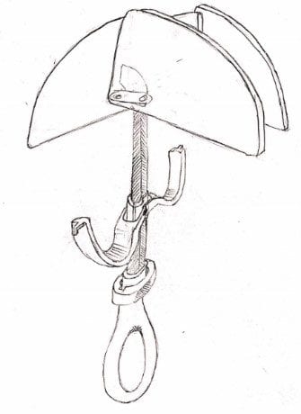
This was one of the initial designs we produced during our brainstorming phase of the project. We used a decision matrix to converge on this combination of trigger, thumb loop, and lock concepts.
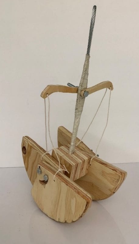
The first structural prototype. It was built from wood, wire cable, tape, string, and two bolts. We built this to see how bulky the final SLCD would be based on early analysis.
Design Concept
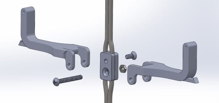
The key component that separates our cam from others is its rotating trigger mechanism. The rotating triggers allows for more lobe contraction with a smaller pull on the triggers. This design was chose because we found that a downfall of other large cams was that they were uncomfortable to use due to the trigger being so far away from the thumb loop.
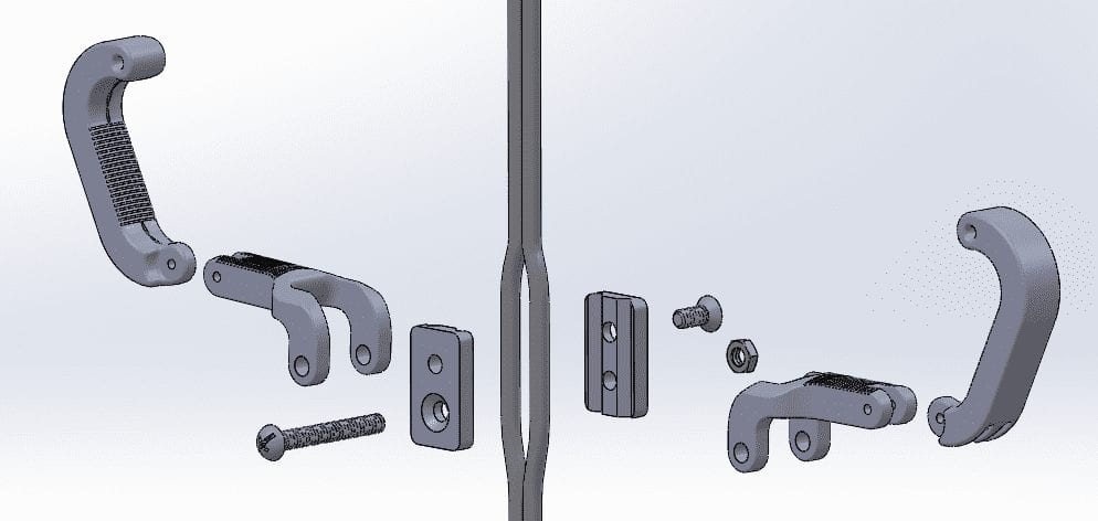
During prototyping, we found that the our first set of triggers were unable to fully actuate the cam’s lobes. So on next iteration, we implemented a double hinge system, which increased the triggers’ pull range of without significantly increasing their size.
Final Design
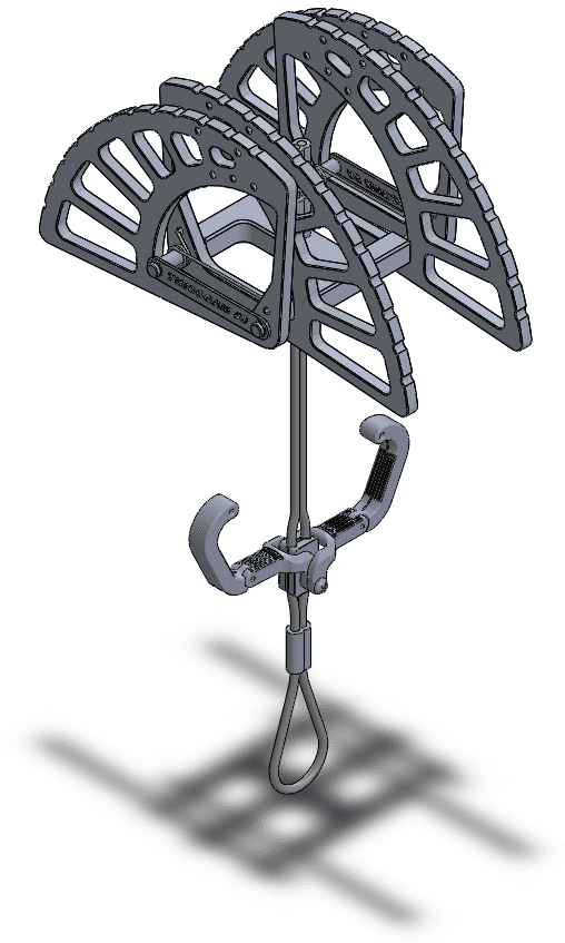
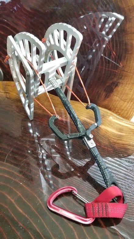
We are excited to present our camming device we call the ThiccCam #9. It is a double axle, 4 lobe cam, with a flexible steel cable stem. The cam is designed for a 14 kN load, weighs 1135 g, and works within cracks between 6 to 9 inches wide.
In addition, we designed the cam to be assembled without power tools, which makes maintenance and iteration easier, as we can simply swap parts between cams.
Custom Components
- Lobes
- Double Hinged Triggers
- Carriage
- Axles
- Axle Linkages
- Lobe Springs
Stock Components
- Wire Cable
- Trigger Wire
- Tiller Clamp (Trigger Mount)
Analysis
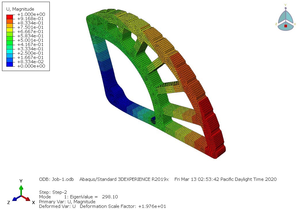
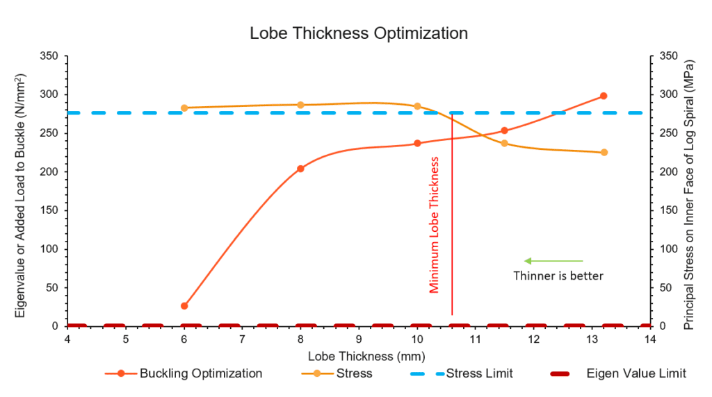
(Top) The visual results from Finite Element Analysis (FEA) on a lobe within Abaqus. By running the FEA model with multiple lobe thicknesses, we were able to improve the size to weight ratio of the overall cam.
(Bottom) Linear buckling optimization curves from the lobe FEA. We found that the lobes would reach yield strength before they would begin to buckle under load. The minimum lobe thickness is about 0.4 inches.
Manufacturing Process and Components
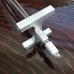
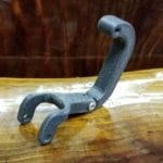
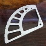
- Lobes, axles, carriage, and axle links were CNC machined.
- Lobe springs, wire cables, and trigger wires were modified by hand from stock materials.
- Triggers were 3-D printed using PLA plastic.
Testing
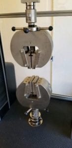
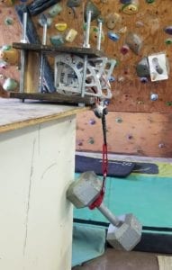
Tensile Test-The tensile test is a key test that is needed to validate our analysis and the performance of the cam. The cam is pulled till failure in three different positions in accordance with international testing standards. Due to COVID-19, we were unable to complete the tensile tests, as we did not have access to the testing facilities on campus.
Stem Bend Test – The bend test ensures that there is no permanent deformation when the cam is bent around a 90 degree corner. We found that our cam passed this test and there was no permanent deformation after the bend.
Field Testing – The device was tested in the field for ergonomics when the device was in use. We found that the cam’s lobes successfully grip the rock wall.
Test Result Summary-
Tensile Strength: Untested
Cost: Pass ($90)
Weight: Fail (1135 g)
Stem Buckling: Pass
Stem Flexibility: Pass
Range: Pass
Recommendations
- Future testing is highly recommended to validate analysis. We are concerned that the cam’s axles could deform under load, so the axle diameter is needs validation using tensile testing.
- More iterations need to be made to meet all of the criteria.
- Lobes and carriage could be optimized further to reduce weight and cost.
- Triggers could use more ergonomic and clearance testing.
- A locking mechanism could be implemented and optimized.
- A stem sleeve could be designed and injection molded to provide stiffness to the stem.

