
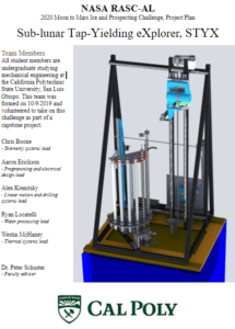
STYX
This project is sponsored by NIA, Baker-Koob, Capstan, and MESFAC


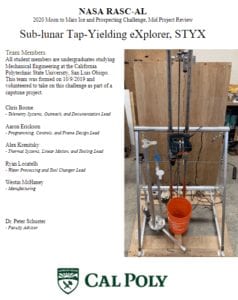
STYX
This project is sponsored by NIA, Baker-Koob, Capstan, and MESFAC

