Our Team

Justin Syracuse
Justin Syracuse is a 5th year mechanical engineer. He plans to utilize his knowledge in the energy industry and hopes to be a part of the large-scale management for solar panel projects. His professional interests include hands on projects, manufacturing, and wood working when he can. His personal interests include baseball, spending time with family, and spending as much time outside as possible.

Donald Syracuse
Donald Syracuse is a 5th year mechanical engineer from Cal Poly focusing on a general concentration. He’s looking to pursue the renewable energy industry when he graduates, specifically solar applications. He’s a native of San Luis Obispo County and enjoys building, hand on activities and spending time with family. Sports are one of his passions especially baseball, being a lifelong Dodgers fan.

Chris Ewert
Chris Ewert enjoys spending his free time working on his van or surfing. When he graduates, he would like to work in the marine engineering industry specifically on remotely operated vehicles. Ideally, he would end up doing conservation work to help protect fisheries and various endangered species. He believes it is his duty on this planet to live a healthy and sustainable life and to change industry practices to be more ecofriendly.

Jason Kehl
Jason Kehl is a 4th year General Mechanical Engineer who currently plans on graduating this Spring. At Cal Poly he has engaged in the American Society of Mechanical Engineers and the Delta Upsilon international fraternity. His professional interests include airflow over aerial vehicles and developing carbon-free energy sources. In his free time he enjoys hiking and camping along the central coast.
Acknowledgements
We’d like to extend a huge thank you to Professor Sarah Harding for her dedication to the Spring 2020 senior projects and the Mechanical Engineering Department, in particular Dr. Andrew Davol and Dr. Jacques Belanger for their technical assistance throughout the last year.
Our Project Videos
Our Project's Digital Poster
Ideation
Design 1: This design utilized a large rectangular base with a rotating bar in the front for tilt, and wheels to adjust azimuth. The panels would be secured in place by several brackets that would mount to the back of the panels.
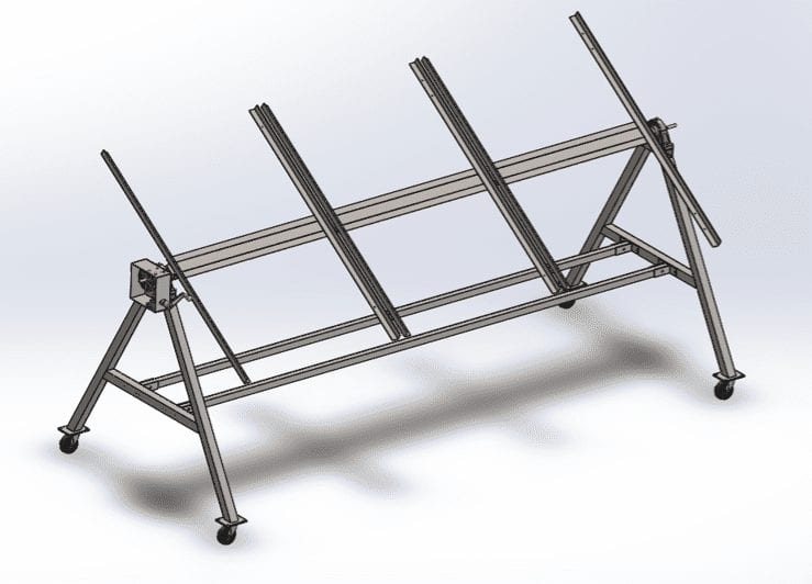
Design 2: This design has an A-frame base that ensures stability, resembles a sawhorse design, and large clamps to fasten the panel to.
Design 3: This design is a single tripod for a base. The legs are stationary, and the azimuth adjustment uses a large bearing as opposed to wheels.
Design Constraints
Specification Description | Requirement or Target | Tolerance |
Weight | 350 lbs. (Excludes Panels) | Max |
Production Cost | $2000 | Max |
Time to Clean | 20 min | Max |
Maintenance Time | 60 min | Max |
Forces/Loads | 90 mph winds | Max |
Demo Survey | Operable by untrained student |
|
Time to adjust | 2 min | Max |
Range of tilt | 15°- 90° | Range |

This Project is sponsored by the Cal Poly Mechanical Engineering Department in conjunction with Pacific Gas & Energy.
Problem Statement
Cal Poly’s new Energy Resources concentration needs a way to inspire and educate students about various renewable energy sources through their micro-grid. We aim to design and build a new solar panel mount capable of holding multiple photovoltaic panels that can be interchanged, so that the instructors can demonstrate efficiency and power output of an adjustable system. This mount will also allow for expanded solar energy research to be done at Cal Poly.
Design Concept
The design incorporates pre-existing solutions, sponsor feedback, and stress calculations of critical components in the system. For simplicity purposes, the design was intentionally driven away from electrical circuitry and complex software programs. The solution uses proven mechanical concepts and an array of mechanical components such as gears, bearings, fastening methods and simple beams.
Design Verification

The rotating cross member was analyzed extensively through hand calculations and finite element analysis to determine the structural stability of the mount in both normal operating conditions and severe wind conditions. A 3 in square cross section of 1/8 in thickness was chosen as it verified minimal deflections in both circumstances. In 90 mph wind conditions (max load) the deflection was 1 in.

The geometrical properties of the A-frame were designed to allow for the full range of tilt specified in the design constraints.
Final Design Breakdown
Specifications
- Weight: 262.99 lbs
- Length: 124.25 in
- Width: 53.15 in
- Height: 50 in
Support Frame

- Various size carbon Steel tubing
- Provide overall stability and durability to design
- Two cross members reduce vertical torque
Mounting Brackets

- Various size angled Carbon Steel
- Direct interface between panels and rotating bar
- Manufactured specific to panel dimensions
Rotating Bar

- 3″ Carbon Steel tubing
- 1/16″ thick
- Holes drilled along the bar to interface with mounting brackets
- Solid steel inserts at each end to interface with pillow bearings
Gearbox and Crank

- Provides increased panel tilt accuracy
- Four gear system
- Overall Gear Ratio: 120:1
- One crank rotation = Three degrees panel rotation
Gearbox Analysis

The Gearbox utilizes a four gear mesh and three different types of gears. The mesh includes
- 60:1 Spur gear to Worm gear
- 2:1 Vertical Bevel to Horizontal Bevel
The overall gear ratio was chosen based on the desired 1° tilt accuracy of the panels. This 1° tilt corresponds to 1/3 of a crank turn. The crank location was decided upon by ergonomic principles and the front face will be transparent acrylic to allow students to understand basic gear analysis.

