Thermal Energy Storage for Load Shifting

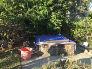
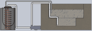
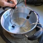
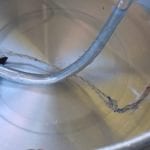
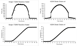
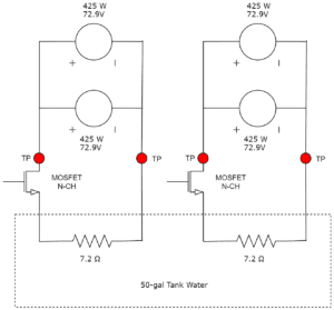
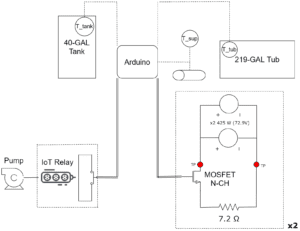
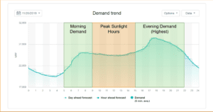
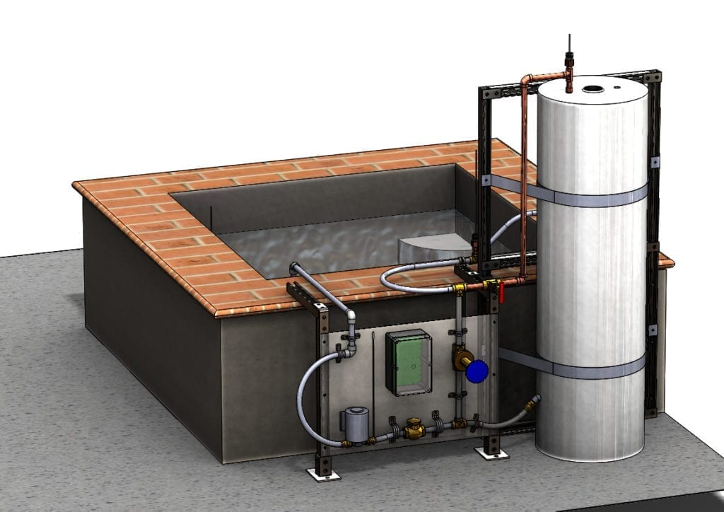
Physics Professor Pete Schwartz has a hot tub in his backyard and four 425 Watt solar panels on his roof. Currently, his panels heat his hot tub directly using resistive heating elements, and he cannot use his hot tub in the evening. Our team, Ra Energy, designed a thermal energy storage system, so Dr. Schwartz can use his hot tub after the sun sets. Energy storage can shift electrical load away from the late afternoon when people return to their homes, and it is a crucial technology necessary to create a sustainable future.

Our Team: Ra Energy

Taylor Harms

I’m a 4th year, transfer student from Santa Maria, CA, and I will be pursuing my Masters Degree in Mechanical Engineering this Fall. I really enjoy backpacking, fishing, and long road trips. I look forward to a career in alternative energy, paving the way to a carbon-neutral economy.

Jordan Lopez Corley

I’m a 4th year undergraduate with a general concentration focused in non-carbon energy production. I am a member of Cal Poly’s Wind Power Design club, and I am seeking employment within the renewable energy industry. In my free time, I enjoy playing Dungeons and Dragons, arranging music, and reading.

Weston Montgomery

I’m a 4th-year blended student concentrating in mechatronics. I’ve been very involved with ASME, Rose Float, and Circle K during my four years at Poly. I enjoy swimming, listening to NPR podcasts, and playing video games. I hope to find a career related to sustainability or commercial spaceflight after I graduate.

Acknowledgements

Huge thank you to our senior project advisor, Dr. Peter Schuster, our sponsor, Dr. Pete Schwartz.


Our Project Videos

Video 1. System Overview

Video 2. Technical Presentation (*CORRECTION: The diagram at 11:37 should show two panels in parallel similar to Figure 9 in the section below)

Video 3. Active Mode System Test

Our Project's Digital Poster

DESIGN PROCESS

IDENTIFYING THE PROBLEM

Figure 1. Dr. Schwartz's hot tub

Dr. Schwartz currently uses two resistive heating elements (Figures 2 & 3) to directly heat his hot tub (Figure 1). These heating elements are wired directly to the photovoltaic (PV) panels on the sponsor’s roof. Unfortunately, with this setup the hot tub cannot be heated at a time when the sun is not hitting the panels, prohibiting evening use of the tub.

Figure 2. Resistive Heating Element (A)
Figure 3. Resistive Heating Element (B)

Design Process

Figure 4. CAD Version 1

The first iteration of our design (Figure 4) utilized a diode chain to directly heat our tank. We sized the chain based on research previously conducted by our sponsor for solar cookers. [1] Through further analysis, we found we would need to construct our immersion heater using 130 diodes and 11.5 feet of aluminum tubing. We ultimately decided to move away from DC diodes because it would be too expensive and risky to manufacture an immersion heater so long. Our original design also incorporated a copper coil to transfer heat from our storage tank to the water being circulated to the tub. We ultimately moved away from the heating coil because we wanted to take advantage of the natural thermocline in the tank.

Diode Prototyping

At the start of our project, we spent a lot of time prototyping a custom diode heating element. Based on research conducted by our sponsor, diode heating elements could be more advantageous than resistive heating elements in cloudier weather and off-peak times (Figure 5).

Figure 5. Current-Voltage Data for Resistor v. Diodes

Through our prototyping, we found the diode design would make our system far less reliable; it would also increase the time and cost of our project. Through further analysis, we also found that both resistive heating elements and diodes would be equally effective during sunny weather (Figure 6).

Figure 6. 1st -Law Transient Resistors v. Diodes

[1] Schwartz, P., 2019, “Hot diodes!: Dirt cheap cooking and electricity for the global poor?,” Development Engineering, Volume 4.

SUBSYSTEMS

PV Heating System Design

Figure 7. PV Heating System Design

Our final design uses two 7.2 Ohm resistive heating elements that are each powered by two 425 W (72.9 Vmpp) panels in parallel. Therefore, our system provides a peak power input of 1476 W to the storage tank until it reaches its set-point of 95 °C. The storage tank is a modified 50-gallon Rheem electric water heater.

Fluid System Design

Figure 8. Fluid System Design

The supply water from the tank mixes with the return water from the tub; this supplies the tub with 46 °C of water. The fluid system is comprised of type L copper, expandable PEX-A, a 1-/10 hp transfer pump, one control valve on the supply line, and one control valve on the bypass line. Copper is used in the sections where high-temp water is present to ensure system safety & PEX-A is used in all other sections to decrease cost and increase manufacturability.

Control System Design

Figure 9. Control System Design

Our control system accomplishes the following:

  • As a safety precaution, the heating elements will always shift off when the tank temperature exceeds 95 °C, and the pump will always turn off when the tub and supply water temperatures exceed 40 or 46 °C, respectively.
  • As an efficiency measure, the pump can only turn on if the tank temperature is greater than the tub temperature.
  • Our system also features an active mode and passive mode.
    • In active mode, our system prioritizes the tub’s set-point of 40 °C.
    • In passive mode, our system prioritizes the tank’s set-point of 95 °C.

We accomplished the above by using one Arduino Uno, four DS18B20 temperature sensors, two n-channel enhancement mode MOSFET’s to switch the heating elements, and one IoT Relay to switch the pump. We simulated this system using TinkerCAD software (Figure 10).

Figure 10. TinkerCAD Simulation

FINAL OUTCOMES

Complete System Design

Figure 11. Final CAD

System Features

  • Minimum tank charge time: 1.5 days
    • Starting temperature: 20 °C
    • Set-point: 95 °C
    • Data: Scaled 100W panel current-voltage from a sunny day in SLO
    • Analysis: Transient First Law of Thermodynamics
    • Assumptions: quasistatic equilibrium, constant specific heat, constant properties at the control surface, insulated tank, incompressible fluid
  • Maximum tub usage time: 5 hours
    • No sunlight
    • Starting tub temperature: 40 °C
    • Starting tank temperature: 95 °C
    • Final tub/tank temperature: 40 °C
    • Ambient temperature: 15 °C
    • Wind speed: 3.62 m/s
    • Analysis: Specific heat and evaporation heat loss equations
    • Assumptions: quasistatic equilibrium, constant specific heat, uncovered tub
    • Safety Factor: 4

Control Box

Figure 12. Control Box

In spite of the Coronavirus Pandemic, our team still managed to build the complete control system (Figure 11) necessary to run the heating elements and pump appropriately. Once our sponsor builds our finished design, he will be able to easily incorporate our completed control system.

Design Verification

We verified our hardware and software behaved as expected through testing. We ensured our safety features always worked; the heating elements shut down when the tank temperature reaches 95 °C and the pump shuts off when the tub reaches 40 °C or supply water reaches 46 °C. We also ensured that in active mode, the pump would turn on when the tank reaches 90 °C. Please see Video 3 for our control system test.

Future Applications

The State of California will soon require all new residential buildings to have solar panels installed and no gas lines. This makes our project very relevant because it allows users to heat up water during the day when sunlight is available and then use that hot water in the evening for domestic hot water and space heating. As solar power generation increases outside California, the duck curve (Figure 12) will migrate outside of our state and thermal energy storage methods will increase in importance.

Figure 13. Demand Trend (AKA Duck Curve)

Recommendations

Our final design enables our sponsor to use his hot tub in a safe, sustainable, and cost-effective manner in the evening. We have a couple recommendations on how our system can be improved after our sponsor finishes assembling it:

  • Have an electrical engineering student design and build a converter which can dynamically lower the current and increase the voltage output of the panels to increase the maximum heat output of the resistive heating elements during less sunny weather.
  • Insulate the hot tub and install a privacy screen to decrease heat loss via conduction and convection.

.

Project Slideshow

Click Here
Previous
Next

Have a Question About this Senior Project?

Send an email to pschuste@calpoly.edu to be connected with the project team. Please include the title of the senior project you’re inquiring about in the subject line.

Interested in Sponsoring a Mechanical Engineering Senior Project?

Visit our Sponsorship Page to learn more!

Check Out More Projects!

Visit our ME Senior Projects Page to view the latest Mechanical Engineering senior projects from the class of 2021!

Share

Share on facebook
Share on twitter
Share on linkedin