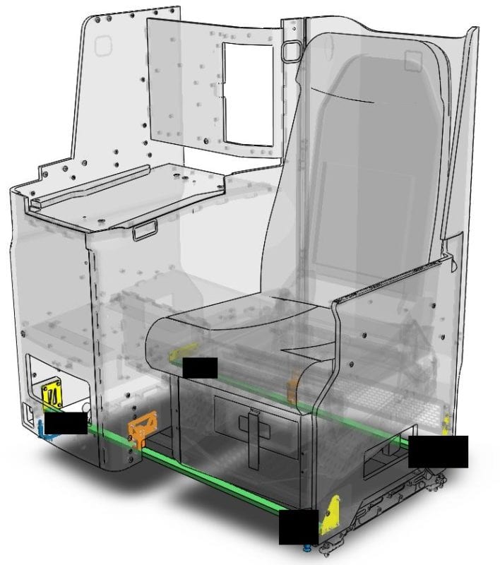
The purpose of this project is to design a universal attachment method to secure a widebody business class seat to seven aircraft models with different seat track geometry. The goal is to design, document, and create a finish product that fits design, weight, and manufacturing requirements.
Some confidential components of this project have been removed to protect the proprietary property of Safran Seats.
Our Senior Project Team

Craig Kimball
ME Mechatronics
Concentration
I am Craig, a 4th year M.E. undergrad. I have automation, manufacturing, and R&D experience from internships with Ernie Ball Music Man a guitar company, and undergraduate research in shape memory polymers from freshman year.
Lynette Cox
ME Mechatronics Concentration
I am Lynette, a 4th year M.E. undergrad. I have manufacturing experience from my position as a senior student shop technician. I also have teamwork, design, and composites experience through the Cal Poly Racing Formula SAE team, as well as R&D and design experience from an internship with Volkswagen.
Tyler Bragg
ME Manufacturing Concentration
I am Tyler, a 4th year M.E. undergrad. So far, I have had 3 internships at Oakley, Callaway Golf, and Full Swing Golf. I plan on being a Quality Engineer for a telecommunications equipment company in the San Diego area after graduating in Spring 2020.
Acknowledgements
We would like to thank our sponsor, Safran Seats Santa Maria, for giving us the opportunity to work on this project. Our team would not have been able to complete the project without the support of Ian Bohannon, lead design engineer for Safran Seats. Thank you for your incredible support and guidance throughout this project.
We would also like to recognize our professor Dr. Elghandour for his non-stop support and project advice throughout the academic year.
Our Project Videos
Our Project's Digital Poster
Problem Statement
Design a universal frame that allows a widebody business class seat shell to be installed onto multiple aircraft seat tracks of varying widths. The product should be able to attach to predefined seat tracks that run the length of an airplane and accommodate the variations in attachment configurations.
Design Constraints
- Withstand 9G FWD dynamic testing to pass FAA requirements
- Total weight of less than 15 lb
- Must fit to current seat shell design
- Does not affect seat pitch or aisle width
- The seat shell must sit 1″ above the seat tracks
- Installable on the seat tracks of any of the following aircraft: A320, A330, A350, A380, B747, B777, B787
- Must be attached to 2 seat tracks with provided floor fittings
- Minimum 4″ gap between floor fittings
- Does not interfere with or have connections to the current seat frame for the passenger seat (separate from the shell frame design)
Seat Frame Layout
The final seat frame layout was chosen for the following reasons:
- Meets all design constraints
- Re-uses parts within the design to reduce manufacturing costs
- Is the most universal option by having the ability to fit all seat tracks and seat track floor fittings without the use of interchangeable parts
Other design choices to note:
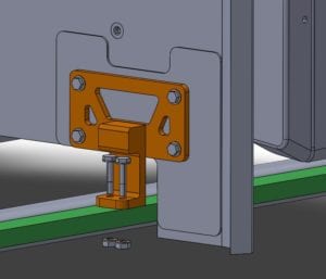
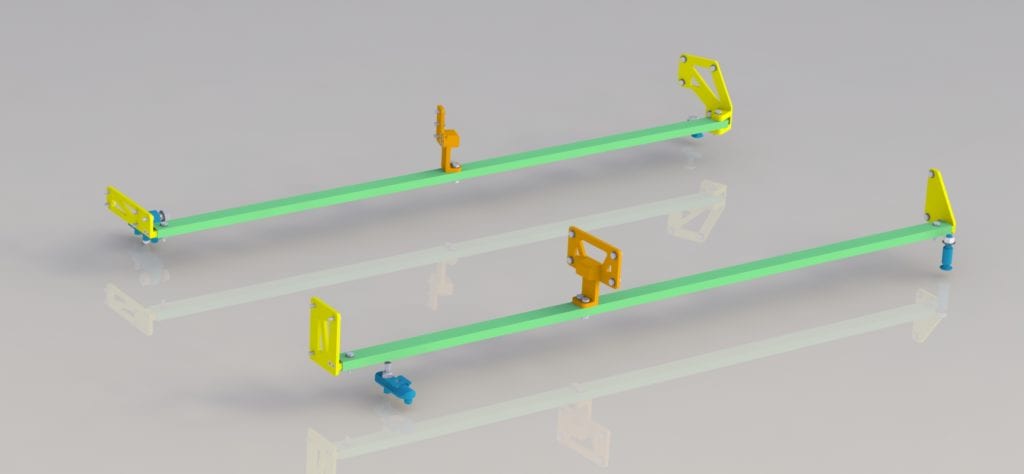
- The design consists of 4 sub-assemblies: Support Beams, Doubler Connectors, Mid-Frame Supports, and Beam to Connector Fittings.
- The front and rear beams are designed to be perpendicular to the seat tracks. This standard allows easier fitment to all aircraft seat tracks.
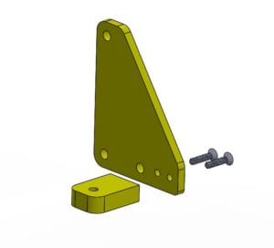
- Doubler tabs are attached to doubler plates using both an adhesive and #6-32 screws to ensure transfer of loads.
- Material choice of 6061-T6 aluminum alloy ensures that the design will be lightweight, easy to manufacture, and strong for its purposes. 6061-AL has a yield strength of 40ksi, and when given a T6 temper it is also an aerospace certified material.
- The final design is meant to be assembled almost exclusively with NAS 1801 #10-32 aerospace grade fasteners.
Design Concept
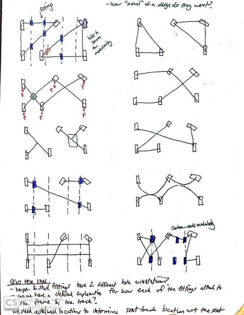
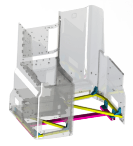
These preliminary models allowed for dimensions of various components to be experimented with, and aided in determining the final seat shell frame layout.
Universal Seat Attachment

Safran Seats, Santa Maria
2019-2020
California Polytechnic State University, San Luis Obispo
Finite Element Analysis
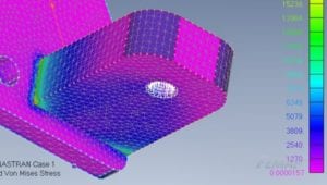
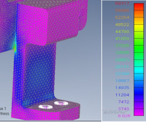
To verify that all components manufactured by the team would survive 9g testing, and to look for areas where the design could be improved finite element analysis was performed on every component of the design. For the analysis FEMAP student edition, a program from Siemens, was used for all analysis work. The goal of analysis was to apply the expected loads to each component and determine if the part yielded. This analysis helped with justification of fillets at different points in the design and served as confirmation of hand calculations performed by the team. Screenshots of some of the results from the FEA are shown below.
Manufacturing Process
Design Verification Plan
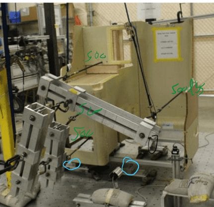
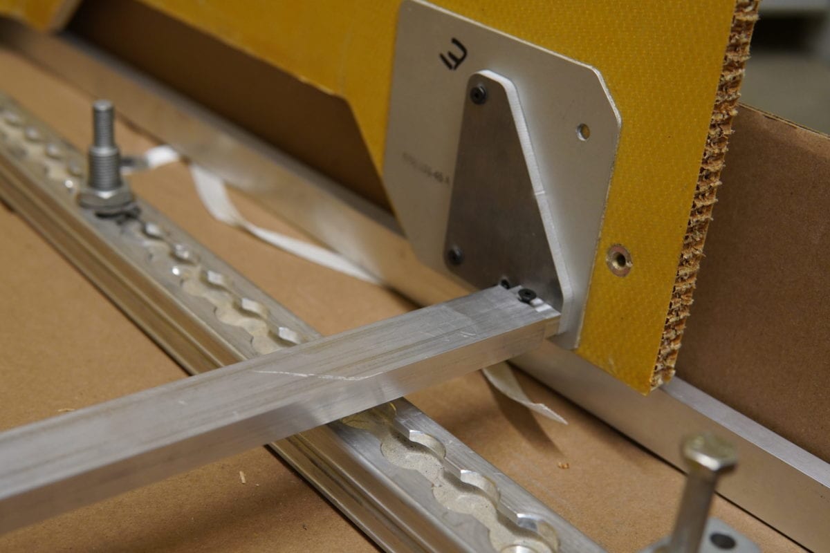
9G FWD Static Load Test- The goal of this test is to prove that the final prototype created by the team can survive the required 9G FWD loading as required by the FAA for the component. This will be achieved by using a static pulling device known as the “Wiffle Tree” to apply a static FWD load to the CG of the entire seat shell assembly.
End Plate Tab Assembly Verification- The goal of this test is to prove that the end-plate tab assembly, which consists of a tab that is connected to a plate via two #6-32 screws and epoxy, is able to withstand the expected maximum loading case without failure.
Installation Time Test- Safran Seats describes the ideal installation time of the full assembly to be under 15 minutes. Not including pre-assembly of each part, the full assembly requires between 17 to 26 minutes to install if two people are working at the same time.
Final Design
Specifications
Weight with Harper/Stud fittings: 5.60/5.72 lbs
A 56% weight decrease from the previous solution.
Material: 6061-T6 Aluminum
Assembly Time: 17-26 minutes
Dimensions: Appx. 40″ x 25″
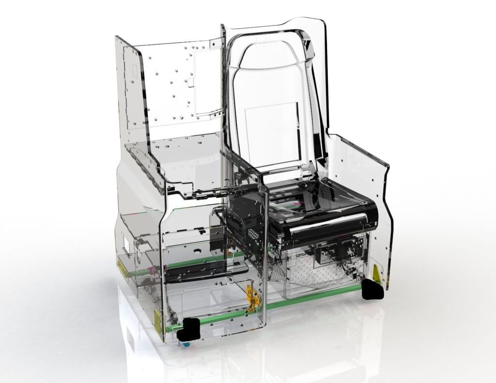
4 Subsystems
- A: Support Beams
- B: Doubler Connectors
- C: Mid-Frame Support
- D: Beam to Connector
Stock or Components Provided by Safran
- Composite Seat Shell
- Harper Fittings + Hardware
- Stud Fittings + Hardware
Future Application
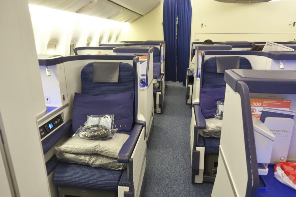
The seat shell that was provided to the senior project team by Safran is a seat design called the Skylounge. The particular design is a seat that is already flying in commercial airplanes, so there is a low chance that the design will be put into production. Rather, this project could benefit Safran’s new platform program.
Recommendations
The team would suggest the following to Safran for potential improvements to the final prototype:
- Change the front and aft beams to be made of circular tube stock rather than rectangular tube stock.
- Modify the doubler plates on future shell designs such that a universal end plate can be used.
- Modify the doubler plates on future shell designs such that the end plates are all at the same relative height.
- Refine the method by which the beams are attached to the seat shell.

