Our Team

Karthik Padmanabhan
Project Manager
Karthik Padmanabhan is a mechanical engineer from Saratoga, CA. His main roles were design analysis, testing protocols, website design, and project management, including communication with sponsors and managing the project timeline. Karthik also worked on the expanded CAD setup.

Craig Icban
CAD Engineer
Craig Icban is a mechanical engineer from Temecula, CA. His main roles were design analysis, CAD modeling, manufacturing, and testing. Craig also troubleshooted manufacturing issues, created the expanded CAD assembly, and ensured mechanical functionality of the final prototype.

Scott Mangin
Mechatronics Engineer
Scott Mangin is a mechanical engineer from Dublin, CA. His main roles were design analysis, testing, and design of the electrical systems for the test fixture. Scott is responsible for coding and wiring the electrical subsystems.
Acknowledgements
We would like to thank Professor Rossman and our sponsors at Abbott including John Szymanski, Stephanie Raymond, and the engineers on the Leads Development Team at Abbott who provided us with guidance throughout the project.
Our Project's Videos
Please enjoy our project overview and design breakdown of our Lead-to-Can Abrasion Tester
Our Project's Digital Poster
Problem Statement
One of the leading causes of a pacemaker system failure is an electrical breach. During the installation of the pacemaker and endocardial lead(s), excess lead is wrapped around the main body of the pacemaker device. An electrical breach may occur when the endocardial lead of a pacemaker abrades against the body of the pacemaker device, wearing through the outer sleeve insulation; this causes electrical pulses to be grounded into the body of the pacemaker and not reach the heart, leading to serious health complications for the patient if not diagnosed and treated. The purpose of this project is to design a bench test fixture to quantitatively characterize lead to can abrasion (LTCA) for Abbott to use in future FDA submissions.
Design Constraints
- Dimensions*: Smaller than 23″ x 13″ x 9″
- Weight*: Less than 20lbs
- Set up time: Less than 4 hours
- Data Consistency: Less than 30% cycle count variation
- Test duration: Less than 175000 cycles
- Fixture must accommodate all Abbott lead diameters
- Final Design must be expanded to test 10 samples at once
- Custom components must be easily manufacturable by Abbott’s machine shop
* constraints set for prototype, not final model
Design Process
The key design feature for the test fixture is the lead abrasion method. Our first step was to decide the most desirable method to abrade the lead. In vivo, the endocardial lead abrades against the body of the pacemaker (known as the “can”) when wrapped around; therefore, to best simulate the conditions seen in the field, the outer insulation on the inside bend (in compression) of the lead must be in contact with the abrading surface in saline (saline is used to simulate blood for in vivo conditions). Therefore, it was important to ensure that all components in contact with the saline are resistant to corrosion.
After brainstorming, we used various decision-making tools to finalize our preliminary design, leading up to a system morphological matrix. This matrix showed that the best method of abrasion to pursue was a rotating cylinder in contact with the lead.
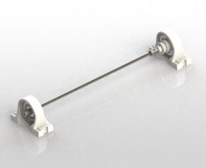
In designing the abrasion cylinder, it was important to get corrosion-resistant bearings that can withstand fatigue testing. It was also vital that the abrasion cylinder was removable for operators to remove and control the surface finish. The pulley shown on the abrasion cylinder links to the DC motor via a belt to drive the cylinder rotation.
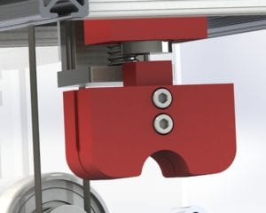
Our focus then shifted to designing a lead holder that will actuate down onto the cylinder. A relief pocket was added to ensure that the abrasion occurs on the compressive side of the lead bend.
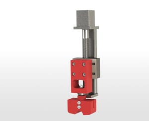
The last major mechanical requirement was to design a method of linear actuation for the lead holder. After brainstorming multiple ideas, including a rack and pinion system, we decided on a lead screw system with a load cell to ensure a precise normal force without constant stress on the stepper motor.
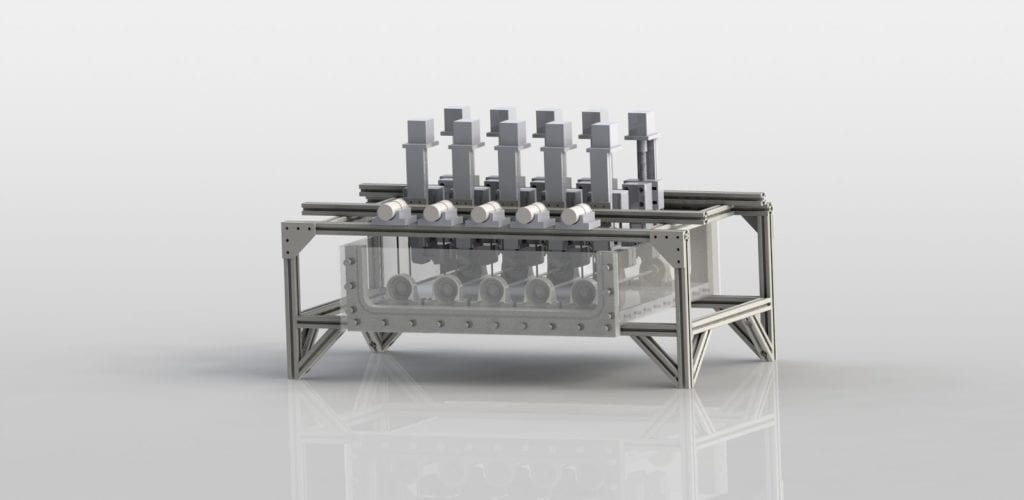
After the major mechanical subsystems were designed, the rest of the design was system based to ensure the fixture will perform as intended. A sealed acrylic tank was chosen since the test is performed in a saline solution. A DC motor was needed to rotate the cylinder, with a Hall-effect encoder attached to track cycle count during the testing process. The lead screw platform system purchased had an attached stepper motor. Both systems were then powered through L298N motor drivers (in different configurations). After the electrical system was finalized, the tester design was completed and implemented.
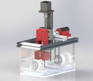
This CAD model allowed for dimensions of various components to be finalized and aided in determining tolerances necessary for manufacturing and assembly.
This project is sponsored by Abbott CRM
Testing
Cycle Count Testing
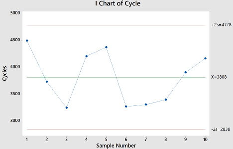
10 Abbott lead samples (sample A) were tested with our functional prototype to quantitatively characterize the lead abrasion performance. As specified in our design constraints, the relative standard deviation (RSD) for our abrasion testing must be less than 20%. The RSD is calculated by diving the standard deviation by the mean of the data.
As seen in the graph above, the mean cycle count for sample A was 3808 cycles with a standard deviation of 485 cycles. Therefore, the RSD is 12.7%, significantly below our requirement of 20%.
This is a significant improvement from the LTCA tester Abbott currently has.
Setup Time Testing
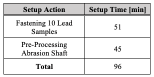
Using our prototype, we calculated the setup time for our expanded setup. This was done by recording the time needed to set up one shaft and one lead sample. These values were extrapolated to match our final design setup of 10 samples and 5 shafts.
From this extrapolation, we calculated a total setup time for our final design of 96 minutes. This is significantly under the requirement of 4 hours.
Therefore, our final design largely improves from the current LTCA tester Abbott uses by reducing the setup time by over 50%.
Conclusion
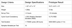
The deliverable of this project is a functional single-sample prototype of our LTCA Tester design with a completed expanded setup design that can accommodate ten lead samples for testing. Despite the challenges faced during the pandemic with limited access to campus resources, we were able to design and manufacture a fully functional fixture that consistently abrades pacemaker leads. Our final prototype and design met all the specifications, as seen in the table below.
Since lead abrasion conducted during bench testing cannot perfectly replicate the abrasion that occurs in a clinical setting, the cycle count value carries little meaning until it is compared against the clinical performance of a pacemaker lead. By comparing the cycle count of leads that have little to no abrasion failure with leads that have had a history of abrasion failure, a reasonable cycle count threshold can be calculated to determine the safety of a lead’s insulation.
From the consistency of our testing results, we can confidently say that this bench test fixture will be able to accurately characterize lead to can abrasion for a pacemaker system, and outperforms Abbott’s current LTCA tester.
Future Considerations
Due to our limited resources and time available for this project, we were unable to test a large number of lead samples to gain a more accurate representation of the cycle count variation. To ensure that this fixture performs the way it is intended to, further testing with more lead samples ( > 30) should be done.
Our prototype could only test one sample at a time. The expanded setup we designed can accommodate 10 samples, and will be the design that Abbott uses for their final tester. We have designed our system and electronics to handle the expanded setup, but we have not attempted to manufacture the system to see how it behaves. This will need to be explored by Abbott.
The key defining parameters for lead abrasion are the surface roughness of the titanium cylinder, the normal force of the lead on the cylinder, and the rotational speed of the cylinder. We have varied these parameters to optimize the cycle count consistency, but Abbott should conduct more studies in this regard with more samples to see what values deliver the highest resolution for cycle count.
Final Design
Specifications
Weight* – 13.4 lbs
Dimensions* – 13” X 10.5” X 6.5”
Custom Components
- Lead Arm
- Lead Holder
- Lead Clamps
- Linear Slide
- Shaft Adapter
- Bearing Mounts
- Motor Mount
Stock Components
- Lead Screw Platform
- Titanium Cylinder
- Motors
- Ball Bearings
- Acrylic Tank
- Aluminum T-Bar
- Screws, Nuts, Bolts, Washers
- Timing Belt Pulleys
All custom components have been reviewed by Abbott to ensure that their shop can machine each part.
Electronics
Our electronics subsystem consists of five crucial elements:
- Arduino Mega 2560 Microcontroller
- L298N Motor Driver
- Stepper Motor (built-in to lead screw system)
- SKU FIT0186 Geared DC Motor with Hall Effect Encoder
- ATO-LC-TC01 Load Cell with HX711 Amplifier

The micro-controller provides logic to the tester by: operating the stepper and DC motor in a closed-loop feedback system, providing cycle count data, and detecting breaches in the lead.
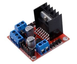
The L298N motor driver is necessary to deliver the required power the motor needs to operate. The motor driver powers both motors using different configurations.
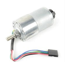
The DC motor powers the abrasion cylinder system and, with the Hall Effect Encoder, tracks the abrasion cycles of the titanium cylinder.
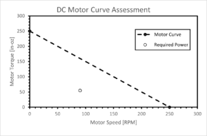
To decide on the motor used for both the normal force and the abrasion cylinder, we calculated the force necessary for our system to operate at a certain desired acceleration. The lead screw system was able to support an actuation force much greater than our lead attachment system, so further analysis was not necessary.
After analyzing the linear actuation system, we then examined the DC motor abrasion cylinder system for the necessary torque required for the SKU FIT0186 motor. After analyzing the system, we saw that the DC motor successfully fulfilled the system requirements at the desired speed of 90 RPM.
Manufacturing
Due to COVID-19, manufacturing did not take place at Cal Poly. All manufacturing occurred at a private residence in San Luis Obispo without campus resources following off-campus manufacturing guidelines.
The first step for manufacturing the prototype was building the acrylic tank and sealing it so that saline will not leak out.

Without access to a machine shop, we 3D printed all the custom components of our design for our final prototype. For the abrasion cylinder system, the motor mount and bearing mounts were printed and connected to the system using screws.

Our last manufacturing step was to integrate the lead screw system and the lead holder with the rest of the prototype. The lead holder was 3D printed and fastened to the lead screw assembly before being attached to the rest of the fixture.
