3-Axis Reaction Wheel System for CubeSats

The goal of this project is to create a functional 3-Axis reaction wheel system for CubeSats through Cal Poly CubeSat Lab based off of preliminary design and research done by a previous Cal Poly masters student. A CubeSat is a very small satellite, around the size of a loaf of bread, that is developed and launched into space for education, research, or scientific purposes. A reaction wheel is a critical component of attitude (or orientation) control of a satellite that consists of a flywheel attached to a motor. When spun, the reaction wheel imparts a change in momentum (or impulse) on the satellite in order to adjust the satellite's attitude in all three axes of orientation.

Our Team

Our team consists of Rose McCarver, Pablo Casillas, Alex Lee, and Daniel Leon. We are all fourth-year Mechanical Engineering majors with a general concentration and are part of the Mechanical Engineering team of Cal Poly CubeSat Lab (CPCL).

Rose McCarver

I am a fourth year mechanical engineering student beginning the blended master’s program. My thesis will be focused on aerospace structural design, reflecting my passion for the industry. Furthermore, I am an active member of both the Cal Poly Machine Shops and the Cal Poly CubeSat Laboratory. These practical experiences have shaped the way that I design for manufacture; with my CAM and CNC experience helping to drive the manufacture of our senior project. I have worked at General Atomics, Northrop Grumman, and will soon begin a co-op at SpaceX working on propulsions in the coming school year. After returning to Cal Poly and graduating from my Master’s in Fall 2023, I will be looking for a full-time position as a Mechanical Engineer in the aerospace field. 

Casillas.Christopher Pablo

Christopher Pablo Casillas

I am a fourth-year mechanical engineering student with a general concentration and will begin the blended master’s program in Fall 2021. My interest in the space industry began when I joined the CubeSat Laboratory where I have been the Mechanical Engineering Team Lead for the past two years. I have had the amazing opportunity to lead the development, design, and assembly of numerous spacecraft and one that is on the launch pad waiting to go to space. I have completed an internship at Lockheed Martin Space Systems in Denver, Colorado where I will be returning this summer. 

Alex Lee

I am a fourth-year mechanical engineering student with a general concentration. I have a special interest in the space industry which is why I spent my last summer interning at General Atomics Electromagnetic Systems in Centennial, Colorado working on small satellites. I had the amazing opportunity to work with structural analysis software and provide aid to the analysis team on the OTB-3 (Orbital Test Bed-3) mission. After graduating in the spring of 2021, I will be starting a full-time job as a Satellite Mechanical Engineer at the same company and location as my internship. I am extremely grateful to be returning to my hometown in Colorado and enjoy hiking and skiing, although I will miss the beach and the beauty of the Central Coast.

Daniel Leon

I am a fourth-year mechanical engineering student with a general concentration and will begin the blended master’s program in Fall 2021. I have wanted to work in the space industry since I was young, which is why I joined the Cal Poly CubeSat Laboratory during my second year. I have been fortunate to have the opportunity to work on several amazing projects within the Lab, some of which are either currently or will soon be in space. I will continue to work in the CubeSat Lab until I graduate in Fall 2022, after which I will be looking for a full-time position as a Mechanical Engineer in the space industry. 

Acknowledgements

We would like to thank our senior project advisor, Dr. Andrew Kean and our project sponsor, Dr. John Bellardo from the Cal Poly CubeSat Laboratory for supporting this project throughout this year. Their dedication and commitment to our success is what made this project possible. 

We would also like to thank Nick J. Bonafede Jr., the masters student whose thesis, Low-Cost Reaction Wheel Design for CubeSat Application, was the foundation of our research and design.

Our Project's Video

Our Project's Digital Poster

Problem Statement

Purchasing reaction wheels from other companies is expensive and difficult to customize. Therefore, the Cal Poly CubeSat Laboratory needs a way to manufacture, assemble, and test their own reaction wheels for satellite positioning which will be integrated into a wide variety of future Cal Poly CubeSats. 

Acronyms & Definitions

  • CPCL: Cal Poly CubeSat Laboratory (also referred to as PolySat)
  • ADCS: Attitude Determination and Control Systems
  • Attitude: Spacecraft orientation in space
  • CubeSat: A classification of small satellites (typically the size of a loaf of bread, classified by 1U, 2U, 3U, etc. corresponding to a 10 cm x 10 cm x 10/20/ 30 cm satellite)
  • Bus: The main structure exoskeleton of the CubeSat

Design Constraints

  • Achievedesired performance metrics for reaction wheels (i.e., forces and energy constraints and torque output) 
  • Affordable (< $2,000  total) 
  • Manufacturable using the  Cal Poly Machine Shops 
  • Shall survive launch and on-orbit environments   
  • Shall meet typical mass budgets provided by launch providers 
  • Shall be able to interface with a standard CPCL Bus structure 
  • Shall be able to fit in less than 1U volume (10 x 10 x 10 cm)
  • Completed prototype and build by end of year 
  • Can be implemented in a variety of CubeSat projects

Specifications

  • Max 165 g per assembly
  • Total assembly must be < 10 cm x 10 cm x 5 cm
  • Must sustain 60 deg C for 6 hours or 70 deg C for 3 hours in thermal testing and 1*10^-4 Torr in vacuum testing
  • Max torque of 1.0 mNm
  • Momentum bit of 17.5*10^-6 Nms and 5 mNms total momentum
  • Must be balanced to a quality of G2.5
  • Must sustain vibration testing to NASA GEVS profile for satellite component

Design Process & Selection

Design scope:

  • Since a majority of the design of the flywheel and motor was done by the master’s student, our design selection focused on the housings. It was important to our sponsor NOT to change the design of the flywheel and motor

Function Concept Sketches

Singular assembly with section view
3-Axis Assembly with partial flywheel coverings
"Clip in" motor with exposed wheel

Some key functions we identified for the housing system were ensuring safety, protecting internal components, mount the reaction wheel system to the bus, restrain undesired motion, retain structural integrity, and orient reaction wheels in an effective orientation. Using these key functions and design constraints we were able to narrow down designs focusing on the most important constraints being versatility and manufacturability.

Original 3-Axis Design by Nick Bonafede

The above design incorporates the flywheels with the motors and is encapsulated in an outer housing; however, this outer housing did not meet specifications of machinability, and we thought by making each reaction wheel separate, there would be more versatility.

Verification Prototype

Stainless steel flywheel with 1 mm test shaft

Our verification prototype was a 316 stainless steel flywheel that allowed us to test not only the manufacturing process and precision but also to test a press-fit between the flywheel hole and motor shaft using a test shaft 1 mm in diameter. The verification prototype testing can be seen in the Preliminary Testing section.

We also 3D printed a prototype to test the assembly and visualize the pieces of the reaction wheel system (seen below).

3D Printed Prototype (front)
3D Printed Prototype componenets

Concept CAD

The selected final design reflects the key functions that the housing system needs to perform: protect the internal components, retain structural integrity, and have versatility. The final design consists of three individual assemblies that can be placed anywhere in the satellite for versatility and compatibility of a variety of CubeSat designs. Additionally, the open concept design where the flywheel is showing reduces the overall mass of the assembly but the x-bracket still protects the other components of the satellite from damage if the reaction wheel fails. Lastly, we chose the inner housing used to cover to be made from a superalloy called HyMu-80 that will protect the other satellite electrical components from the electromagnetic field from the motor.

Reaction Wheel CAD (front)

The outer housing is shown in green, x-bracket is in yellow and attached with #2-56 screws, flywheel is pink, inner (motor) housing is shown in purple.

Reaction Wheel CAD (back)

View of mounting holes for #2-56 screws and motor end cap (blue).

CAD Model Exploded View

This CAD model shows the exploded view of the reaction wheel assembly with all of the parts and material labeled.

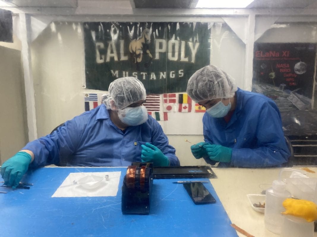
Cal Poly CubeSat & ME Department

This project is sponsored by Dr. John Bellardo with the Cal Poly CubeSat Lab (CPCL) and Dr. Andrew Kean with the Cal Poly Mechanical Engineering Department.

Manufacturing & Assembly

CNC Mill and LAthe Operations

The manufacture of the wheel, part of the motor endcap, and the outer housing all utilized the CNC Mill for various operations. A custom set of soft jaws was developed to fixture the cylindrical inner components, and the tight tolerances required a lot of practice, wear compensation, and a few broken tools. The most precise component in the assembly was the 318 Stainless Steel Flywheel, however space requires tight tolerances on all parts for proper mass specs.

The cylindrical components were manufactured on the CNC Lathe, able to get the best cylindricity for the motor housing and endcap that house the motor. The greatest difficulty was using trial-and-error to determine accurate feeds and speeds for the HyMu-80 material. After many hours of practice, the proper settings for facing and turning were determined and can be used for future iterations of this project.

316 Stainless Steel Flywheel
Aluminum Outer housing (front)
Aluminum Outer housing (back)
Exploded View of Reaction Wheel Assembly (from left to right: flywheel, motor housing, maxon motor, motor housing endcap)

Outsourced Manufacturing

The only components to be outsourced for manufacturing were the x-brackets. These were made out of Aluminum 6061 sheet metal and cut via waterjet in the Mustang 60 machine shops.

Assembly

Note: Assembly details and pictures cannot be shared due to ITAR regulations

Design Verification

Preliminary Testing

Flywheel and shaft structural prototyhpe test press fit
Second hole press fit

One of the main challenges of this project was to figure out what type of fit to use between the 1 mm motor shaft and flywheel hole. Ideally, we want a tight interference fit to ensure the flywheel is centered on the shaft, but we risk bending the shaft when press-fitting. In order to ensure this doesn’t happen, we conducted press fit tests with a structural prototype flywheel. These tests were successful, however, after further consulting experts, we determined the chances of bending the motor shaft are too high with a press fit and we decided to go with a clearance fit with shaft-locking adhesive or epoxy.

Tests Performed

Shaft Load Proof Test- In order to test the fit between the hole of the flywheel and the 1 mm motor shaft test disks and shafts were manufactured using 316 stainless steel and cured using a shaft-locking adhesive called RiteLock RT-48. The fit is a clearance fit with an extra 0.5 thou room for the shaft-locking adhesive. The results were that the RT-48 did not cure as expected, so 3M Scotch-Weld Epoxy was tested because it has been proven in other CPCL applications and verified for flight. This epoxy did cure and we were able to perform a proof test with the test shafts and disks. We used a force gauge in an arbor press to apply force through a force pin to the shaft only and see if it slipped.

Shown above is the shaft load proof test setup with an analog force gauge place in an arbor press using a wooden block. A force pin is located exactly on the 1mm shaft surface and load is applied to the shaft only while the test fixture holds the disk in place. 

Pictured above are the results from one of the shaft load proof tests. The shaft displaced slightly when tested up to its max load so for the actual proof test we determined that the shaft should be tested to slightly under max load. 

Design Verification Continued

Wheel Balancing-The flywheel was delivered to Electronic Balancing Co. in Long Beach, CA to be balanced so that the center of mass of the flywheel perfectly aligns with the shaft. This process verified that no extra disturbance torques will be created when running the wheel up to 50,000 rpm. The image below shows the set up for the balancing test with the computer screen displaying the residual imbalance to be corrected. 

Balancing Setup at Electronic Balancing, Inc in Wilmington, CA

The images above show the wheel after balancing. Approximately 2.5% of the mass was removed from the front plane and back plane.

RPM and Performance Testing- In order to validate the torque output and momentum bit, we ran the wheel through a speed profile (shown below) and verified its performance using the on-board Hall effect sensors on the maxon motor. The wheel was able to accelerate up to 60,000 rpm (higher than the max rpm necessary) and produce a max torque over the required 1.0 mNm.

Torque vs. Speed Graph Post-Blancing (Reference is before removing mass and response is after removing mass)

Final Design

Specifications
Weight – 65.45 g

Max Torque – 1.1309 mN-m (pre -balancing: 1.1892 mN-m)

Wheel Diameter – 0.826 in

Volume – 23.81 cubic cm

Custom Components

  • 318 Stainless Steel Flywheel
  • HyMu-80 Inner Motor Housing
  • HyMu-80 Motor Endcap
  • Aluminum Outer Housing
  • Aluminum X-Bracket

Stock Components

  • #2-56 fasteners
  • Maxon EC-10 8W Brushless Motor
Maxon EC-10 8W Brushless Motor

Future Applications

Upon completion of our benchmark performance tests, we have demonstrated that the assembly has been successfully machined, balanced, and assembled and can produce the required torque and speeds necessary for future missions. This indicates that we have prepared a flight-ready reaction wheel that can be used in conjunction with two more reaction wheel assemblies for full 3-axis attitude active control on a CubeSat flight mission varying from a 1U size satellite up to a 3U size.  This attitude control technology can be developed by students at a low cost and will enable the Cal Poly CubeSat Laboratory to pursue more projects with attitude control and pointing requirements at an aggressive or attractive price compared to our competitors.  The machining process and assembly guides we have developed will enable students to machine, assemble, and balance and fully integrate this technology on future spacecraft. 

Rendering of three reaction wheel assemblies integrated into a 3U CubeSat
Rendering of interface between reaction wheel and bus

Conclusions and Recommendations

In conclusion, we have designed, assembled, and tested a Reaction Wheel Assembly that has successfully undergone balancing, and has passed all of its preliminary benchmark tests to meet its target torque and momentum required to position a spacecraft. 

The next step for the project is to validate the same benchmark tests of the wheel in an “on-orbit” environment similar to what it will experience in space through testing in a thermal vacuum chamber. As well as validating its ability to endure the vibrational launch environment through vibration table testing.

Due to the possibility of potential issues arising in the balancing and assembly process the team only machined and assembled a single Reaction Wheel Assembly. If the Laboratory ever desires to use this 3-Axis control system the machining, balancing, and assembly of two more Reaction Wheel Assemblies would be necessary. The team is confident in the machining and assembly guides we have created that this system can be replicated by a future team. 

Our Project Gallery

Have a Question About this Senior Project?

Send an email to pschuste@calpoly.edu to be connected with the project team. Please include the title of the senior project you’re inquiring about in the subject line.

Interested in Sponsoring a Mechanical Engineering Senior Project?

Visit our Sponsorship Page to learn more!

Check Out More Projects!

Visit our ME Senior Projects Page to view the latest Mechanical Engineering senior projects from the class of 2021!

Share

Share on facebook
Share on twitter
Share on linkedin