Team Robot Leg Motion

Photos of the members of the F11 senior project team
Senior Project team F11 Robot Leg Motion is composed of 4 graduating mechanical engineers: Patrick Ward, Ben Spin, Connor Bush, and Tai Mitchell. This team is dedicated to working with our sponsors, Charlie Refvem and Simon Xing, to develop a control system for the motion of a jumping robotic leg.

Our Team

The members of Team Robot Leg Motion are interested in the application of mathematical modeling and electrical mechanical systems. Working with Cal Poly Legged Robot Club, we make up the software design team for a quadruped robotic leg capable of basic motion. 

Image of Patrick Ward

Team Member

Team Lead

Patrick Ward is from Modesto, California. He is interested in robotics, automation, and mechatronics. Patrick is graduating in the spring of 2021 and will go on to pursue a Masters in ME.  

Image of Connor Bush

Team Member

Control Designer

Connor Bush is a 5th year ME with a minor in Physics. He is interested in the fields of robotics, controls, and system dynamics. In his free time, Connor like to hike, bike, and camp. 

Image of Ben Spin

Team Member

Hardware Lead

Ben Spin is from Grass City, California. He will graduate from Cal Poly in the spring of 2021 with a B.S. in Mechanical Engineering and a concentration in Mechatronics. Ben enjoys biking, playing guitar, and hiking. 

Image of Tai Mitchell

Team Member

Control Designer

Tai Mitchell is from Kauai, Hawaii. He is graduating from Cal Poly in the Spring of 2021 and will begin working in Fremont, California. Tai’s interests are in sustainable practices and environmentally friendly solutions. 

Acknowledgements

This project would not have succeeded without the help of our faculty advisor, Peter Schuster, and our project sponsors, Charlie Refvem and Simon Xing. Additionally we would like to thank our fellow researcher Bradley Kwan for helping us develop and debug our mathematical models and controller.

Our Project Video

The following video is a brief overview of the scope of this project. The video will introduce the need for this product, our approach to this controller design problem, and our final design and tests. For more information, refer to the project’s digital poster below. 

Our Project's Digital Poster

Project Definition and Sponsor Needs

CAD Rendered Design of Robotic Leg on Test Stand

The Problem: 

The goal of this project is to develop a way to control the locomotion of a single robotic leg. The potential applications for this robotic leg include rescue missions and last mile delivery. 

Sponsor Needs: 

As an ongoing research project, our controller design needs to be repeatable and easy to use for future students. Our sponsors wanted us to develop multiple mathematical models of the robotic leg for the same system. Additionally, they wanted us to develop a control method for a robotic leg to hop vertically while constrained by the test stand. 

Path Input

To operate our controller, the user will input the desired hip and knee positions using Cartesian coordinates. These inputs are accepted by two constant blocks at the start of the control loop. Using a Mux block, the inputs are combined into a vector and passed to the inverse kinematics function. Inverse kinematics outputs the corresponding joint angles that the robotic leg needs to produce. To calculate these angles, we used the system properties, current leg position, and desired leg position.

All corresponding angle position, velocity, and acceleration data is passed to the feedback linearization block as the desired motion.  

Simulink Diagram of Path Input Subsystem

Feedback Linearization

Feedback linearization determines the torque required to move the leg into the desired position. This is done by using the angular data generated by the initial conditions. Feedback control is the intermediate step that allows one to find the desired torque input. Using the desired joint angle values, the current motor position, and the system parameters, the feedback control determines the required angular velocity. 

The feedback controller outputs the required angular velocity and then passes this data to the feedback linearization function. 
Block Diagram Connection of Feedback Controller to Feedback Linearization

'Plug and Play' Plant Design

The ‘plug and play’ plant model can simulate the system, using the torque output generated by the feedback linearization. We modeled our motor gains as simple gains because they contain built in controllers from the manufacturer. The motor gain is passed into the model representing the system. The Lagrangian is used to model the system, in the image below.

 We designed our controller so that the model could be swapped out with either the Newtonian or Multibody models. The only requirement is that the model accepts torque inputs and outputs the angular position and velocity of the leg. These output values are used in the input section and feedback linearization to control the motor. 

Simulink Diagram of System Plant

SPONSORS

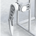
This project is sponsored by Professor Simon Xing and Charlie Refvem. They combine their disciplines of mathematical modeling, and electrical mechanical interactions to form the Cal Poly Legged Robots team.

Modeling the Leg

Schematic of leg

Below is the schematic that we used to model the SDOF leg. The leg is attached to a test stand so that it is constrained to vertical motion. The foot is assumed to have a no-slip condition, allowing it to remain at a fixed distance (X) from the test stand. We measured angles from the horizontal at the knee and the hip. In the diagram, m1 and m2 represent the masses at the hip and knee, respectively. Each model employed this schematic as the system.

Our control system is based on the tracking of joint angles, theta 1 and theta 2, seen in the diagram below. 

Mathematical Model of Leg on Test Stand

Models

newtonian Model

The Newtonian model uses Newton’s Second Law to derive the equations of motion for the leg in terms of the angles theta 1 and theta 2. The equations of motion are determined from the sum of moments and sum of forces at the hip and the knee. These governing equations account for the torque applied from the motors as well as the mass of the motors at the hip and knee. 

Additionally, the hip is fixed to move along a vertical line to mimic its condition of being attached to the test stand. Similarly, the foot is assigned a no slip condition which constrains the foot (point F in the schematic) a distance X from the test stand. 

Newtonian Model
Newtonian Animation for Robotic Leg Motion

lagrangian model

The Lagrangian model uses conservation of total kinetic and potential energy. By assuming that there is no friction in the system, the total energy in the system must remain constant. Defining the kinetic and potential energy in terms of the independent variables θ1 and θ2 allows us to accurately account for the motion of the leg. The Lagrangian is defined as the difference between the total kinetic energy and total potential energy. The Lagrangian is then analyzed to determine the equation of motion for θ1 and θ2.

Lagrangian Equations of Motion

multibody model

Simscape Multibody is a simulation tool operated through MATLAB Simulink.  The Multibody model predicts the robotic leg movement based on joints, solid geometry blocks, constraints, and axis transformations. 

By adjusting leg parameters and applying initial conditions, we simulated the movement of the robotic leg and collected angular positional data to compare to other models. Joint blocks track the movement of the hip and the knee as they respond to the initial torque input. By tracking the knee and the hip, we can plot the movement of theta 1 and theta 2 versus time. 

Final Iteration of Multibody Block Diagram

Final Design

Sdof leg controller

Control Loop Final Iteration

The image above is the final controller we designed for this project.  Please refer to the photo gallery for a listing of the final controller components that make up our design. 

The user determines a path the hip must follow by selecting hip and knee angles. These inputs are then passed to the controller. The controller then takes this path and outputs torques to the motors at the hip and the knee. Encoders in the motor return the actual angles of the leg, which are then used in the control loop. With help from our sponsors, we designed a state space controller to allow for feedback linearization. 

Testing and Results

The following tests verify that our controller design has met the specifications set by our sponsors.

DOcumentation

Proper documentation of our design process means that future students will be able to understand the tools we’ve created. In order to document our work, we created a user manual for our control loop and different models. To test our documentation, the user manual was presented to our sponsors, club members, and peers. After reading the user manual, each test group was presented with an evaluation survey.

Results of Documentation Survey

code optmization

The purpose of this test was to verify that our controller code was optimized to run in an acceptable range. For the robotic leg to function properly, computation speed needs to be optimized. This procedure tests the control loop,  newtonian, lagrangian, and multibody models. 

code
Results of Code Run Time for Final Control Loop

realistic modeling

The realistic modeling test is a crucial verification test of our design process. This test verifies that our three models of the robotic leg reflect real-world conditions. This test also confirms that we were able to approach our controller design problem from different directions and achieve comparable results. The angular position of theta 1 and theta 2 were compared from each model in this test. 

Comparison of Hip Position with Initial Angles and Torque

position control

The position control test was our primary tool for evaluating our controller performance. The test specifically focuses on the position trajectory control feature of our design. Using our final iteration of the control loop, an input path designated such that we could monitor the angle of the thigh and the shank. The passing criteria was to control the hip and knee within 1 degree of the desired path.

Final Control Loop Hip Position Output vs. Input

Conclusion and recommendations

To date, Team Robot Leg Motion has completed model verification, documentation, and animation of SDOF leg controller. Key design verification tests such as controller position control have been met to sponsor specifications. An Issue that should be considered when reviewing this design is singularities. Singularities will always be present in this design because there are configurations that are not possible due to our constraints. Additionally, take note that motor gains may have to be updated. The assumptions made for motor gains in this model may change with hardware implementation. Lastly, controller code optimization may present future issues. Our current run time is based on a MATLAB simulation, which does not accurately represent the realistic speed of the controller. Refer to the Team’s user manual for additional information on operation. 

Controller Components Gallery

Have a Question About this Senior Project?

Send an email to pschuste@calpoly.edu to be connected with the project team. Please include the title of the senior project you’re inquiring about in the subject line.

Interested in Sponsoring a Mechanical Engineering Senior Project?

Visit our Sponsorship Page to learn more!

Check Out More Projects!

Visit our ME Senior Projects Page to view the latest Mechanical Engineering senior projects from the class of 2021!

Share

Share on facebook
Share on twitter
Share on linkedin