The SAVER: Navigation and Controls Team
Ethan Miller
Ethan Miller is the the radio beacon detection lead for SAVER N&C. He oversaw the implementation of the KerberoSDR system for SAVER

Josephine Isaacson
Josephine Isacson is the GPS susbsystem lead. She implemented the GPS code necessary for real time tracking of SAVER in connection with the NVIDIA Jetson

Joshua Hoye
Joshua Hoye is the Visual detection lead. He oversaw the development and implementation of the Jetson based image recognition and the setero camera based depth mapping protocol

Tyler Jorgensen
Tyler Jorgensen is the SAVER: Navigation and Controls team manager. He oversaw weekly meetings, planned and assigned tasks, and coordinated with the SAVER: Body and Packaging team.
Acknowledgements
The SAVER N&C Team would like to recognize and thank Professor Sarah Harding for being our incredible advisor throughout thispast year. We wouls also like to aknowledge the great work done by the SAVER Body and Packaging team for their hard work on the body of SAVER
SAVER N&C Digital Poster
Project Overview
NASA Micro-g Next
SAver competition
The goal for our project was to create a prototype autonomous boat that would be able to locate and navigate to an astronaut in the ocean by detecting a distress beacon emitting a radio signal. The SAVER craft would then deliver first aid supplies, water, and other rescue equirpment prior to the arrival of a rescue crew
The Kerberos System
The KerberoSDR system provided the team with a cost effective way of prototyping radio beacon locating.
By utilizing a set of four antennae for the radio direction finding, SAVER can identify the phases of the wave emitted by the beacon. These phases are then compared between these four antennae and processed by this device called the KerberosSDR which outputs a bearing towards the beacon.
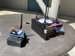
Figure 2: The testing radio beacon (left) with the KerberoSDR system (right)
KerberoSDR Testing Results
We were unfortunately limited by our hardware; the resolution of our devices made it difficult to get accurate readings, and as a result we spent lots of time fine tuning and tweaking parameters. Because of this, we ended up doing smaller, ongoing tests as parameters changed, rather than focus of completing the final protoype prior to doing a full test.
The first step for the KerberoSDR tests was to register the beacon radio wave with all 4 antennae and identify the phase. The signal received at the antennas is shown below in Figure 4.
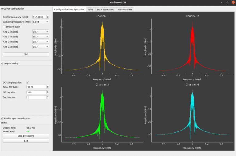
Figure 4: Beacon signal at each of the antennas
Next, these signals were processed and, with the known positions of the antennas, a rough estimation of the signal direction is calculated. This bearing estimation is shown below in figure 5.
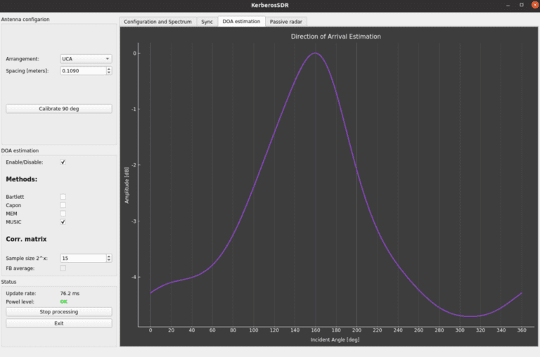
Figure 5: Calculated bearing angle estimation output
Finally, this bearing estimate is combined with the current GPS coordinates a custom mapping software to calculate the estimated beacon location. This location estimation map is shown below in figure 6.
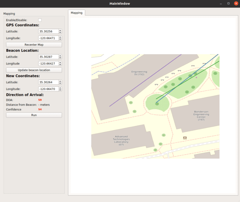
Figure 6: Custom mapping software with beacon location estimate

SAVER Navigation and Controls
Ethan Miller, Joshua Hoye,
Josephine Isaacson, Tyler Jorgensen
Subsystems Overview
The SAVER system consists of many different subsystems, all combining into the complete SAVER device.
KerberoSDR: Radio beacon detection. Used for long range detection and navigation
NVIDIA Jetson: Stereo camera based detection. Used for short range navigation (less than 50 feet to target)
GPS: Used to accurately track and update the location of SAVER in real time
GPS System
Adafruit Ultimate GPS:
By using the Adafruit ultimate GPS module, SAVER was able to accuratelt locate, track, and update it’s location in real time.
Additionally, the GPS was connected to the NVIDIA Jetson using UART communication, and relayed up to date GPS data to the systemwith a frequency of 1 Hz.
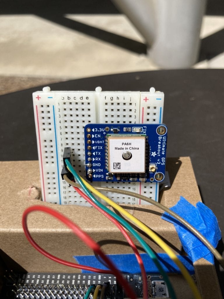
Figure 3: The Adafruit GPS module (top) attached to Jetson
GPS Testing Results
To test the GPS accuracy of SAVER, we attached the GPS-equipped Jetson to a laptop computer, and ran the program to output the GPS position estimate once every second. The GPS was then placed at 8 separate locations and compared to the GPS reading of a cell phone at each location.
The GPS proved to be very accurate, with the greatest difference in the Jetson and cell phone positions being 2 feet, aside from a single outlier with a 31 feet difference. The Jetson/cell phone GPS data comparison is shown below in figure 7.
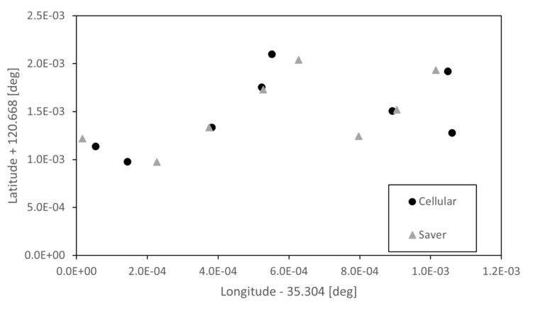
Figure 7: Difference in GPS position between Jetson and cell phone
Conclusions
Our system reached its limits when trying to compile the subsystems into a coherent system. This was caused by the performance limitations of the subsystems along with the lack of collaboration on code due to the COVID-19 pandemic. Going forward, our goal is to create a package and plan to put next years SAVER team in a better position starting out.
Although our project didn’t reach the level we hoped it would, the knowledge and experience we gained from the process was indispensable and will hopefully set up future teams for even greater success.
NVIDIA Jetson
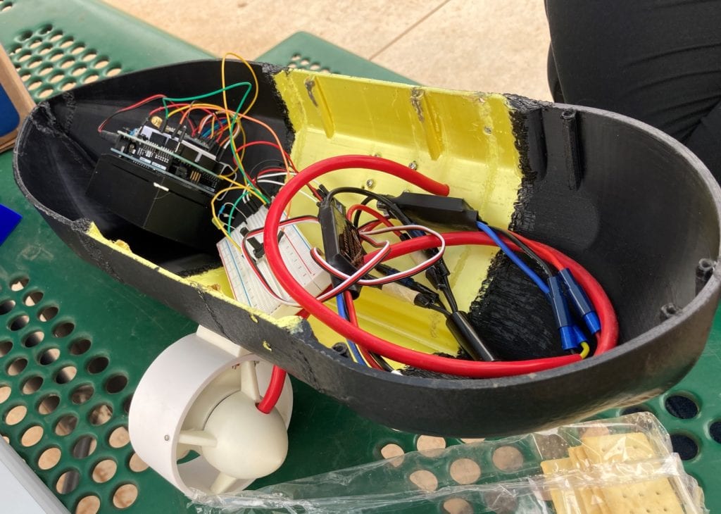
The NVIDIA Jetson is a small, powerful computer capapble of image recognition and depth mapping, as well as combining the incoming data from all of the SAVER subsystems. Additionally, the Jetson was paired with a stereo camera (a camera module made up of two cameras set a small distance apart, allowing the cameras to mimic depth perception).
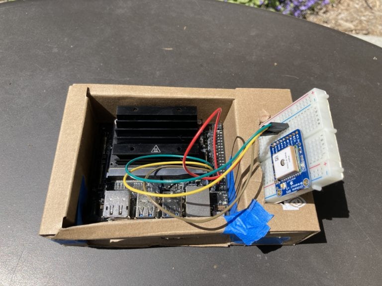
Figure 1: the NVIDIA Jetson with GPS Module attached (right)
Depth Mapping
By using a stereo camera, we were able to use the capabilities of the Jetson to create a depth map of SAVER’s surroundings. This was done by comparing the differences between the images taken from each camera, and calculating the depth of the objects.
Image Recognition
- Built in Jetson capability
- Detect when SAVER can see a person
- Output distance to person detected
- Adittionally, track detected object through frame
Stereo Camera Testing Results
Similar to the KerberoSDR, the capabilities and resolution of our hardware proved to be a larger challenge than ever anticipated. The low picture quality of our stereo camera made it difficult to collect accurate and repeatable data, and as a result lots of time was spent fine tuning the system so we could produce meaningful results.
The first step in the depth mapping procedure was to analyze the stereo images and creates a disparity map by identifying any differences between the two. Then, our custom software uses this disparity map to estimate the depth of the items in the field of view.
The stereo image output and resulting depth map are shown below in figure 8.
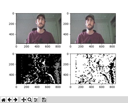
Figure 8: Jetson stereo camera output (top); resulting disparity map (bottom left) and depth map estimation (bottom right)
The other functionality of this system was to use the built in artificial intelligence capablities of the Jetson to identify different object in the view of the cameras. This software was able to identify people and animals in real time, along with generating an estimation of how confident the system was in its estimation.
Additionally, this software was able to track the identified objects as they moved through the field of view, and overlay a bounding box on top of the image of each identified object.
The visual output of this software is shown below in figure 9 and figure 10.
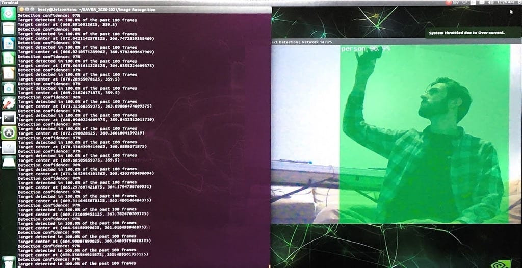
Figure 9: Jetson image recognition code output
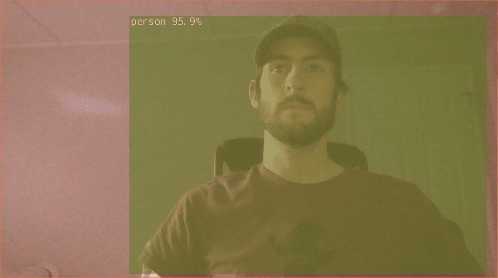
Figure 10: Jetson image recognition bounding box and confidence rating