Team f13
We are team F13, responsible for engineering a low-cost inverted fluorescence microscope for the microfluidics lab at Cal Poly.
Thomas Eggenberger
Thomas is a 4th Year Mechanical Engineering Student and member of the Cal Poly Swim Team. He enjoys working on all sorts of broken bicycles and riding around on his motorbike. This summer he will be working at PACCAR as an OBD calibration intern.

Spencer Hann
Spencer is a 22 year old, 5th year Mechanical engineering student with a concentration in energy resources. Within engineering he is particularly interested in vibrational analysis and structural analysis, and outside of academics enjoys skiing, music festivals, and spending time with his friends. After graduation he hopes to find a job In the field of renewable power generation and eventually save up enough to travel around the world for as long as possible. His most valuable takeaway from his time at Cal Poly is the amazingly loving and supportive friends he made along the way.

Matthew Pfeiffer
Matthew is a 4th year mechanical engineering student concentrating in mechatronics. After this project, he will remain at Cal Poly for two quarters to complete remaining coursework and participate in a physical oceanography research lab on-campus. His favorite aspect of the Cal Poly mechanical engineering curriculum has been the development of an intuition for the physics and mathematics that dictate our natural world. After Cal Poly, he hopes to either continue developing his engineering design and problem solving abilities through industry experience or by pursuing a graduate engineering degree.

Trevor Blythe
Trevor is a SLO county native and transfer student. As a mechanical engineering student concentrating in mechatronics, he enjoys working on projects involving microprocessors interacting with the mechanical world. Upon graduating this spring, he intends to find work in a field where he can continue to learn about and work with these kinds of systems.
Acknowledgements
We would like to thank Professor Mayer for developing this project, and supporting us as a sponsor. He was always helpful and willing to help us in any way necessary, especially in the unique circumstances of remote learning.
We would also like to thank Professor Schuster for supervising us as we worked on this project. He was instrumental in keeping us on track, and providing us with his profesional insights and opinions.
We owe the previous team a tremendous amount of thanks for giving us a solid foundation to work on. Without their work, we wouldn’t have been able to accomplish what we did.
Our stage was anodized free of charge by Neal Feay of Goleta, and we are very appreciative of that. In addition, we made great use of PySimpleGUI python library for modifying the user interface, so thank you.
Microscope Description and Demo
Our Project's Digital Poster
Our Goals
Our team was lucky enough to have a solid base from which to work on. During The 2019-2020 academic year, another senior project team began work on an inverted fluorescence microscope for Dr. Mayer.
Starting where they left off, our Project had three primary goals all of which were met.
- Reduce Microscope footprint and improve electronics packaging
- Increase positional accuracy of the microscope stage
- Improve Microscope usability
Design Specifications
- Footprint smaller than 4’x8′
- No exposed electronic components
- Microscope repeatability within 10 Microns
- Microscope training time takes less than 2 minutes
Footprint Reduction
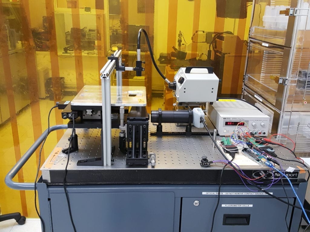
The microscope in it’s original form was significantly larger than preferred by our sponsor.
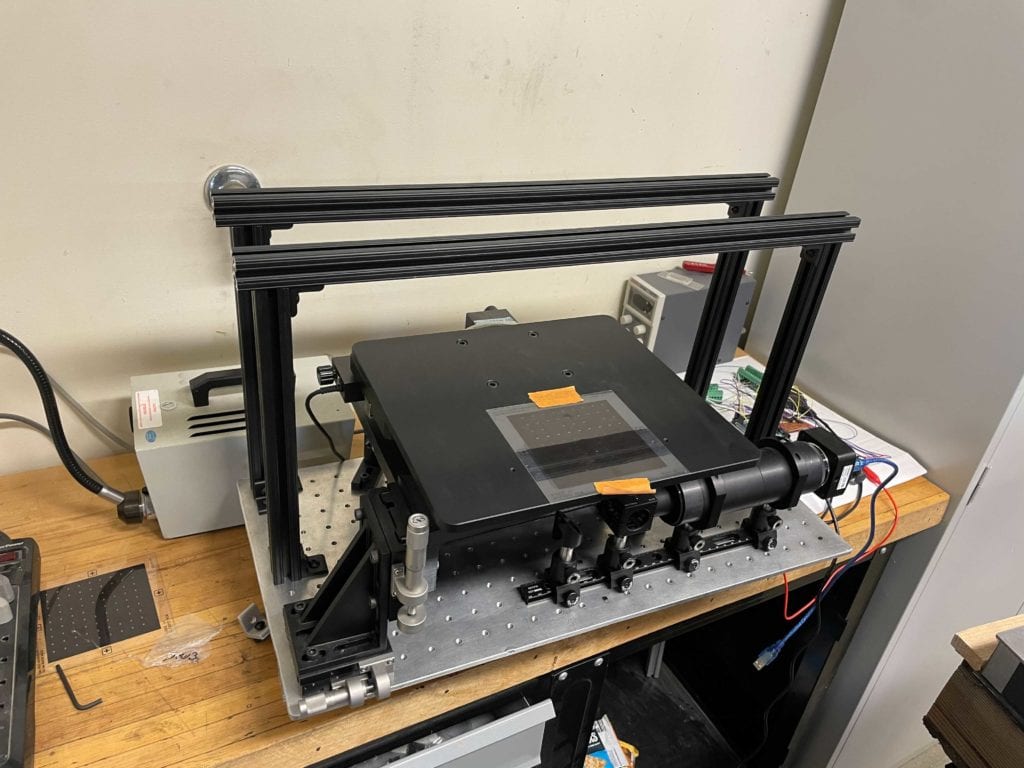
The components were rearranged and placed on a smaller optical breadboard, resulting in a much smaller footprint.
User Testing

Students who had not used the microscope were provided with the user manual and access to the microscope. Testing demonstrated that basic use of the microscope is simple and intuitive.

This project is sponsored by Hans Mayer and the Microfabrication Lab
Repeatability Testing
If the microscope moved along a predetermined path, and then attempted to move to the original position, there would be a noticeable difference in where it ended up. Our first task was to develop and perform a test to characterize this error. We coded an automated test program to actuate the stage a specified number of encoder counts across the entire range of motion of the stage. Then using the serial monitor of the Arduino the error was collected and analyzed
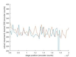 After improving the control scheme by tuning the sample rate of the encoders and the speed differential function and implementing overshoot correction the final repeatability numbers are shown below.
Average Error – 1 Micron
Total Variance – 20 Microns
Electronics Packaging
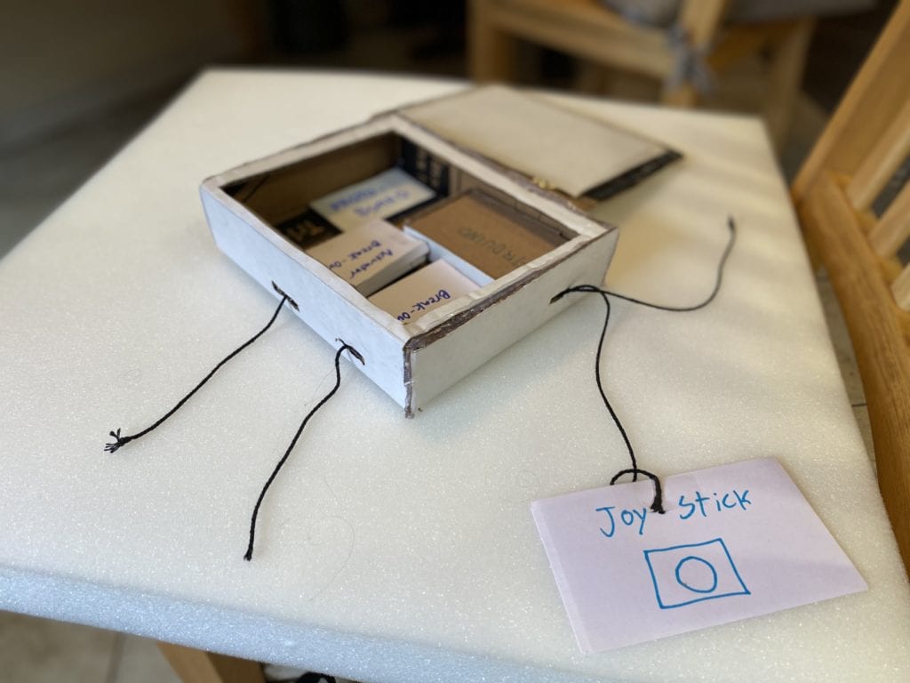
An early electronics housing prototype, made to scale.
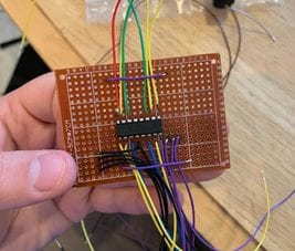
The circuit board was prototyped using protoboard, to ensure our design functioned before ordering custom circuit boards.
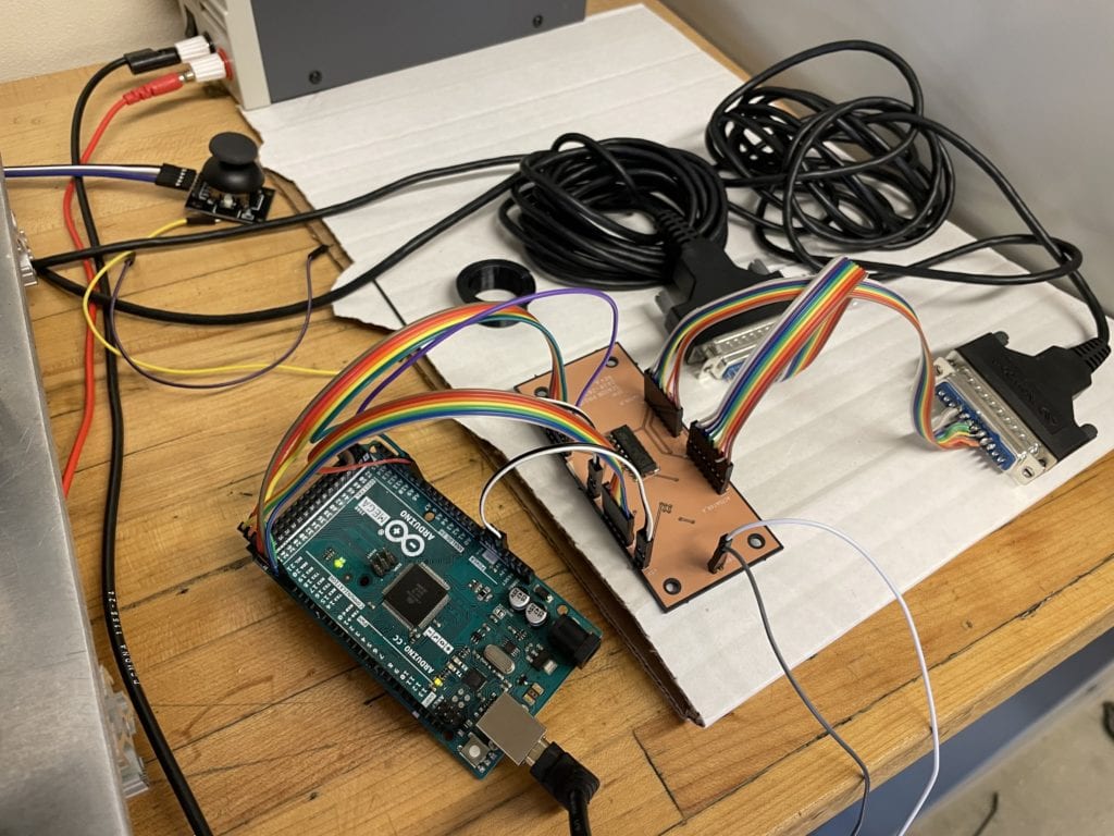
A custom PCB was designed, to minimize the size of the packaging, and to increase it’s robustness.
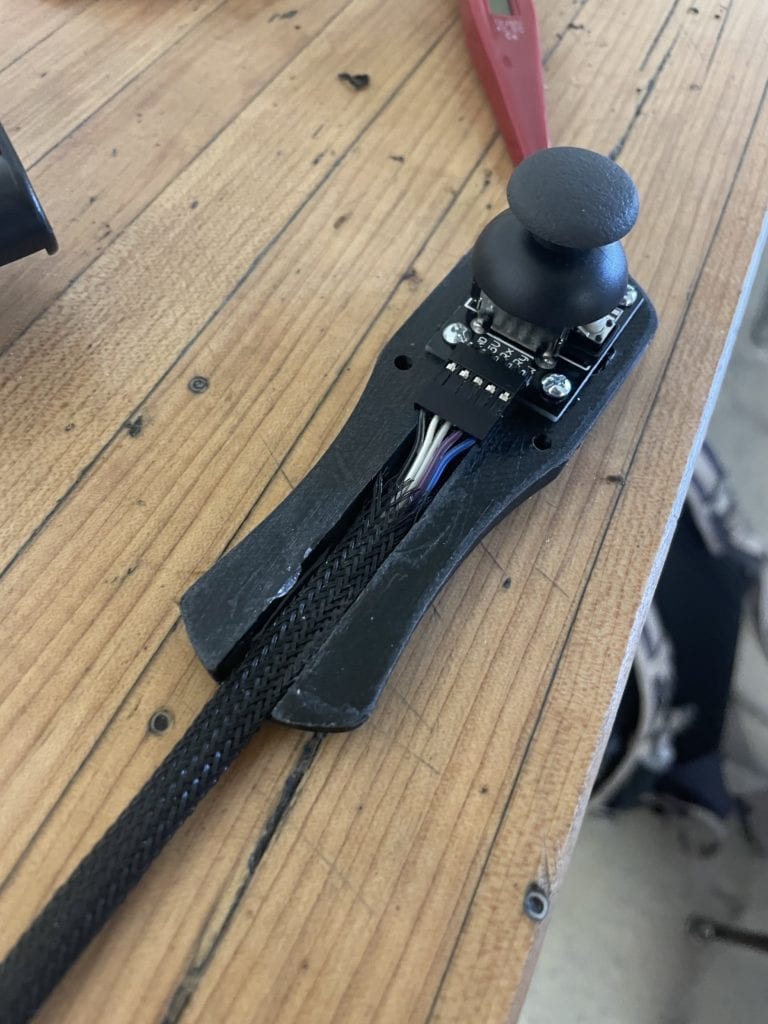
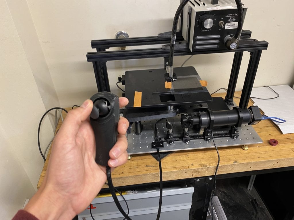
The joystick is housed in a 3D printed housing, for ease of use.
Final Design
GUI Development
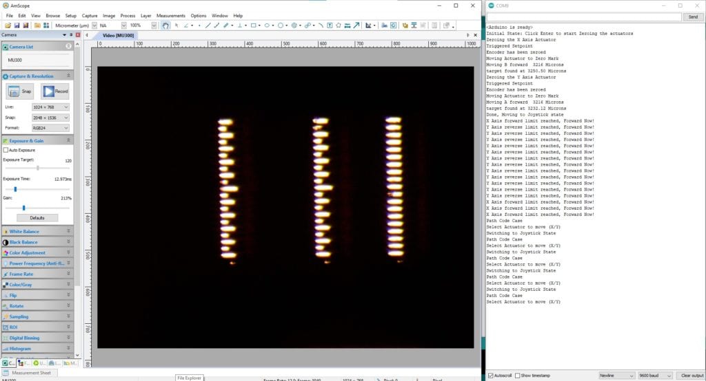
The initial user interface above required the use of a command line, which was not intuitive for new users.
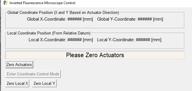
A graphical user interface was developed, so that the primary functions of the microscope could be used without having to type in commands.
Hardware Improvements
The microscope was fully functional in the state we found it, but had some room for improvement.
Extruded aluminum was used to solidify the mounting for the illuminator. Additionally, a 3D printed bracket was used to stabilize the light coming from the illuminator.
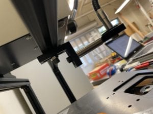
3D printed brackets were used to improve the stability of the illuminator.
Future Improvements
The microscope is fully functional, but there is a lot of room for improvement with the software. Professor Mayer intends to reach out to the CS department for assistance in improving the user interface, and implementing more features in the programmable path mode. Potential features to be added could include the ability to take multiple pictures along a programmable path, or edge detection to automatically trace a feature.
The hardware is fully functional, but potential improvements could be made to the rigidity by adding parts machined from aluminum. In addition, the breadboard could be anodized in a flat black color, so as to improve the look and to prevent light from reflecting off of it and onto the sample.
Conclusion
The final design of the microscope provides a robust and simple to use microscope for a fraction of the cost of a commercial microscope. It can now be used for student research in the microfabrication lab, where it will further the opportunities for future students.

