


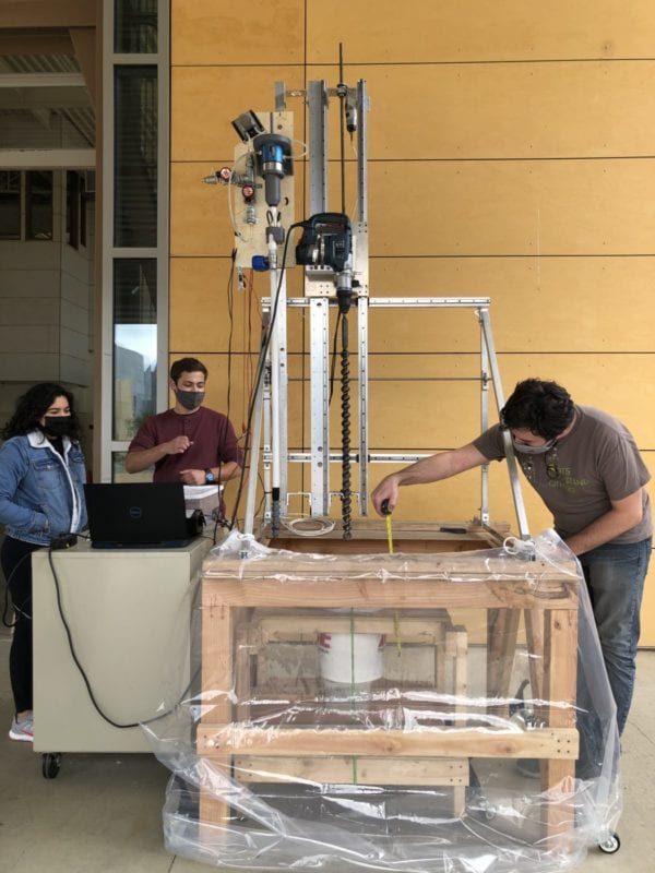
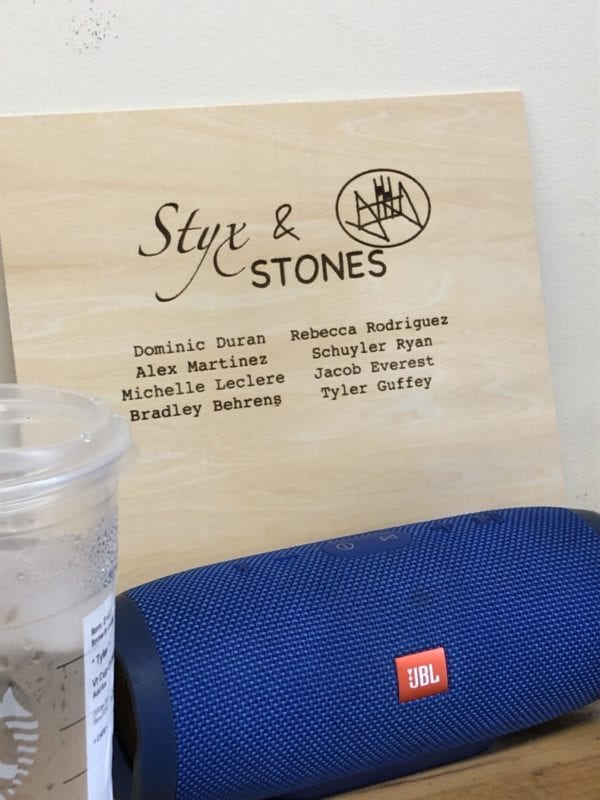
STYX & STONES
This project is sponsored by NIA, Capstan, and MESFAC

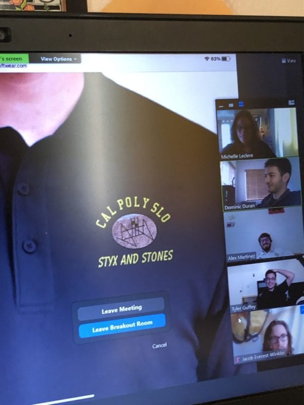
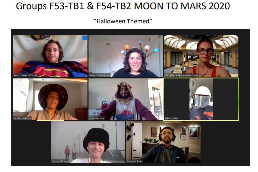
Michelle Leclere

Alex Martinez

Dominic Duran

Brad Behrens

Schuyler Ryan

Tyler Guffey

Rebecca Rodriguez

Jacob Everest


STYX & STONES
This project is sponsored by NIA, Capstan, and MESFAC


