Our Team
This is the Outer Ear Team! We have spent a whole year together designing and building our balancing pack senior project

Ben Presley
Mechanical Engineer
Head of the software development for this project. Interfaced communication with project sponsor.

Connor Sexton
Electrical Engineer
Contributed to the software development and head of the electrical design and components for this project.

Dana Choy
Biomedical Engineer
Contributed to the wearable design, head of the housing design and prototype testing.

Miles Young
Mechanical Engineer
Contributed to software development and prototype testing, head of the wearable fabrication process.
Acknowledgements
We would like to thank Charlie Gutierrez, Karla Carichner, Vladimir Prodonav, and Jim Widmann For their support!
Our Project's Videos
These videos are an overview and demo of how our prototype works, respectively.
Our Project's Digital Poster
Introduction
Why is our project important
610,000 Americans have a first time stroke every year (CDC, 2020) and in that population, 88% of stroke patients suffer disorders with balance and gait (IEEE, 2017). Of these patients, some are unable to balance or walk due to neural pathway damages in the cerebellum. So we are here to find a solution to this problem.
Sponsor
Our sponsor is Charlie Gutierrez. He owns Dynawalk, a start-up dedicated to aiding individuals in improving their balance and mobility. He has successfully helped individuals learn to stand and walk – sometimes for the first time in their lives – using his devices. Charlie has created many devices, but his most successful is the Dynawalker. This device allows the patient to relearn motor control in a safe way by taking weight off of their legs and supporting them through a brace that moves with them.
Design
We chose to go with a vibrotactile haptic feedback wearable system as it was more time efficient and inexpensive as compared to a gyroscope balancing pack. Our design is based on the idea of neuroplasticity, where when a part of the brain is damaged and loses a part of its function like balance, if an individual does repetitive actions (develops a habit) like trying to balance again, the brain finds a new location in itself to allow for an individual to redevelop a method to balance again.
- Design Choices
- – 6 motors surrounding body, 4 on hips, 1 on the bottom of the sternum, 1 on the L3 vertebrae bone.
- – Uses a rechargeable battery as it is easier to charge a battery than to replace it.
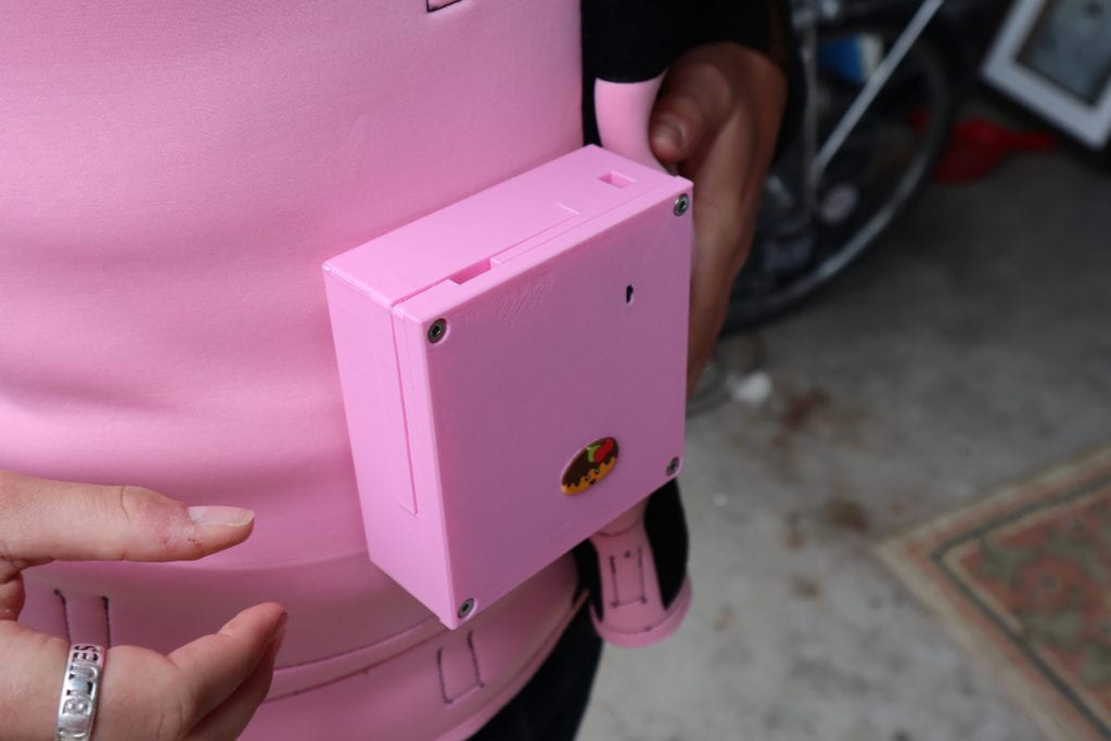
- – Used a small simple 7.1” x 4.7” x 2” box design for the housing with a slight extrude for a pocket of 0.91”x1.44”x0.433” to encase one of the tilt sensors.
- – programmed the microcontroller so that the more an individual leans, the more vibration they feel.
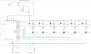
The circuit schematic diagram of the housing, circuitry, and motors to the wearable

Rendered model of the housing for oud design
How the code works
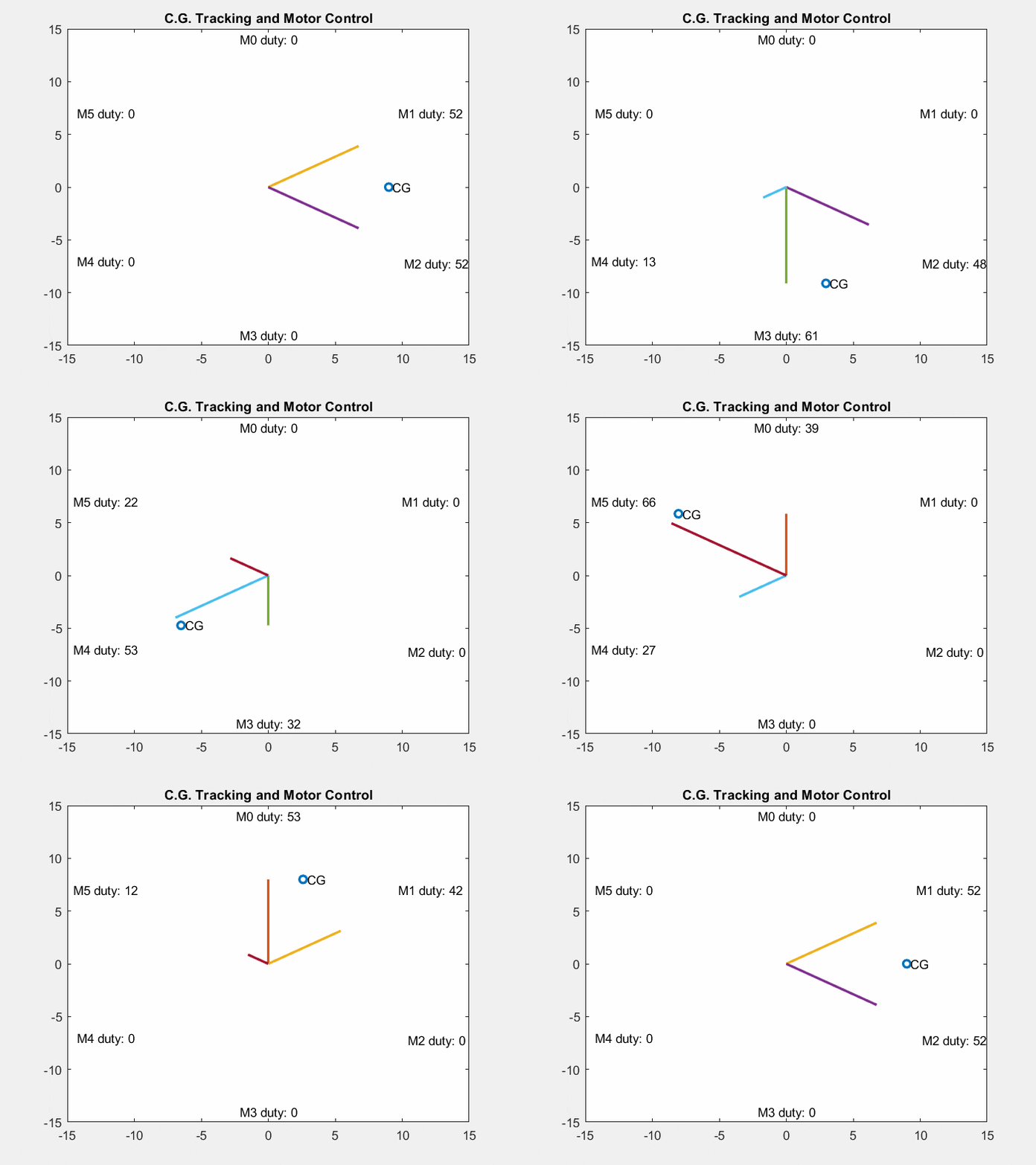
The microcontroller receives an array of data from each of the two sensors, which can be condensed into a 2D angular position of the patient’s lean. This 2D representation of the lean gives us magnitude and direction — a vector!
This vector can be related to the positions of the motor with the dot product. As the patient leans towards a specific motor, that motor will buzz hard, and even harder if the magnitude of the lean increases. Perfect “surround sound” buzzing to help patients feel their balance in a new way. This idea has been simulated with MATLAB in the GIF below.
How the circuit works
The circuit is made mainly from four different parts: The battery controller, the microcontroller, the motor drivers, and the tilt sensors. The battery controller circuit is designed to charge the battery as well as boost its output voltage to 5V so the microcontroller and the motor drivers are able to properly function. The tilt sensors then provide a changing voltage depending on the angle of lean the sensors are at. This data is read by the microcontroller which then sends out an appropriate PWM signal that can control the vibrational intensity based on the duty cycle. The microcontroller uses the tilt data to adjust the duty cycle as well as which three motors need to provide feedback to the user.
Verification Testing
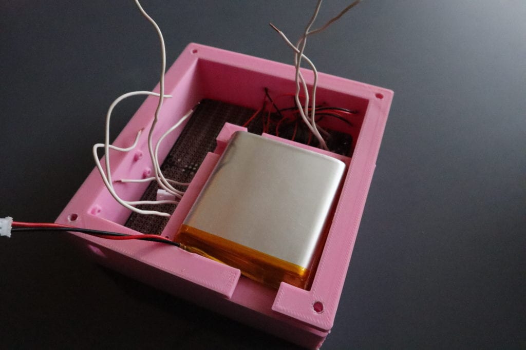
A battery test was done to check the battery lif of the prototype. We essentially allowed for four motors to continuously run and then timed how long it took for the battery to run out of juice. We then also times the battery charging time
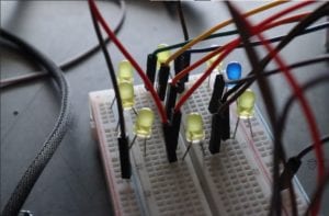
A LED verification test was done by connecting our microcontroller to LED light bulbs on a cookie board. The tilt sensors were then tilted accordingly on a flat platform and the LED light lit up accordingly to the tilt, suggesting that our prototype is functioning properly.
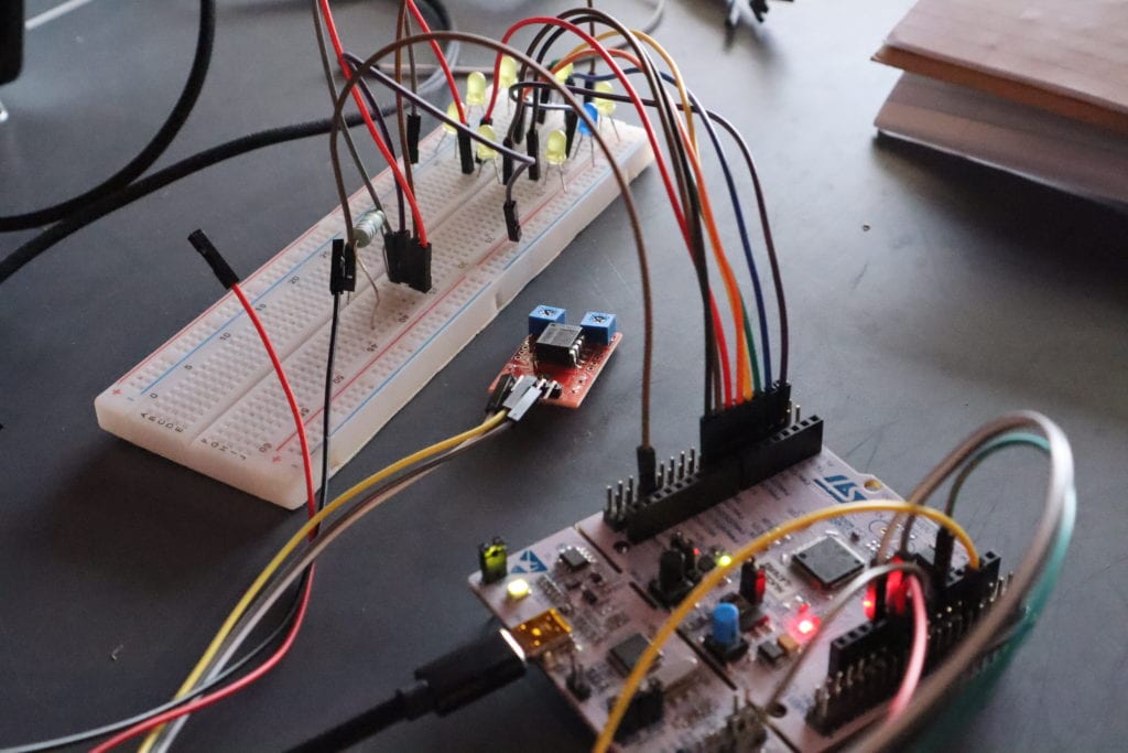
The whole circuitry used for the LED verification testing
Outer Ear Design Team

Manufacturing Process
Programming the microcontroller
All components of the mechatronic subsystems are bought in bulk. Arduino IDE is used to onboard the software to the microcontroller. The code and device parameters can be easily loaded and changed through the microcontroller’s programming port.
Only variation between from part to part within the mechatronic system are the sensors. All sensors have linear voltage-to-degree ratio within a certain angular range, but this range varies slightly from part to part. This is an easy-to-edit parameter in the scripts. A boot-up sequence happens when the device is powered on, which runs through checks and calibrations of the sensors and motors.
Soldering Circuit Board
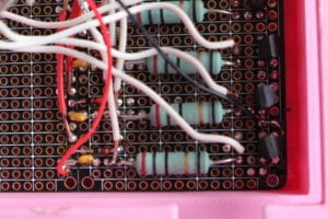
- The circuit board is soldered with standard rosin-core.
- Components that require soldering are the motor driver circuitry, the microcontroller headers, the JST connectors, and LiPo charge boost board.
- Each electrical component has similar source voltage and ground, which allows for easy soldering and circuit board production.
- Currently the top half of the Proto Board contains the six motor driver circuits where we soldered on side by side following the soldering diagram in Figure 1.
- The JST connectors is an extension to the motor so it can allow us to solder it onto the board with the motor in the soldering diagram.
- We also soldered the LiPo charging boost board onto the bottom right corner of the proto board to place it closest to the battery and to keep it close to the rest of the components that need power from it.
- Lastly, we soldered the headers on the bottom left of the Proto Board so that the MCU can be easily installed.
Printing the Controller/Battery Housing
Printing the Controller/Battery Housing
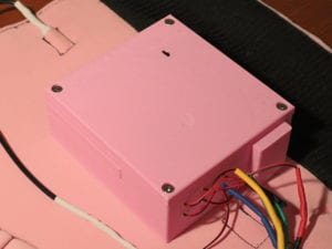
We 3D printed the housing using a standard filament printer at hyper resolution to assure the quality of our product design. The material used for the housing is polylactic acid, PLA, a typical 3D printing material. For the infill density, we set it to 20% for a general balance between weight, mechanical strength, and material costs. The wall, base, and ceiling thickness of the parts are 3mm. The M2 holes were printed as M1.6 holes and manually drilled and taped due to the inaccuracy of the 3D printer.
Sewing The wearable
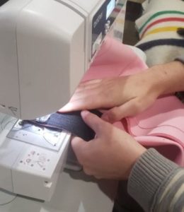
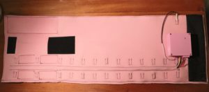
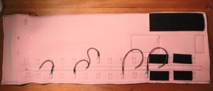
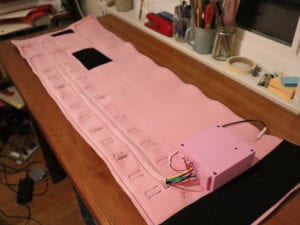
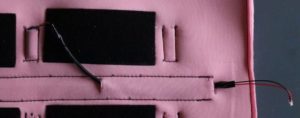
We sewed the wearable with a heavy-duty sewing machine and nylon upholstery thread. The fabric used when sewing was neoprene. We cut the fabric into a 40” x 30” sheet and had the 18 pockets and the housing pocket sown on along with the wire channels before we folded it on the short side to create a double-layered sash.
Final Product
Specifications
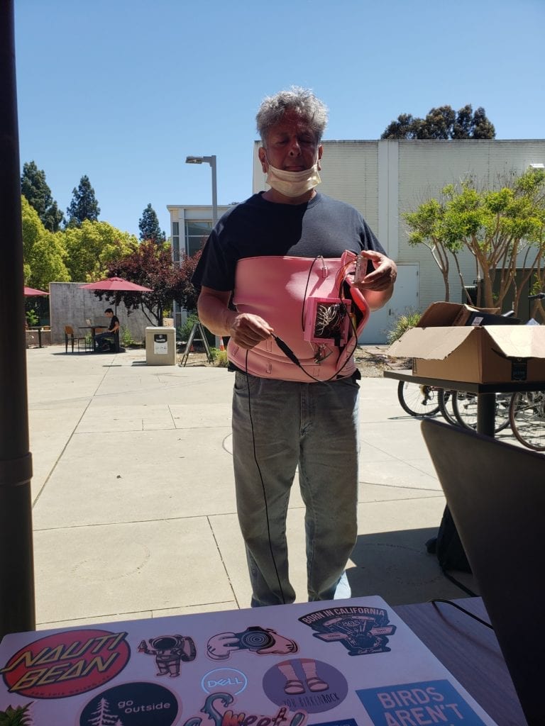
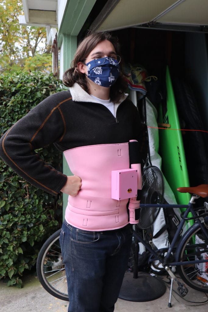
Weight 1.665 lbs
Sash Dimensions 15″ x 40″ x 1/2″
| Components List | Quantity |
| Nucleo STM32L432KC Microcontroller | 1 |
| Adafruit TPS61090 Charging Converter | 1 |
| Homotaxial Tilt Sensor | 2 |
| Vibration Motor | 6 |
| Battery | 1 |
| Circuit Components | 1 |
| Fabric materials | 1 |
| Housing Materials (PLA) | 1 |
| Fastners and Miscellaneous | 1 |
Testing Results
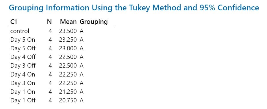
The analysis methods used for the validation testing were through ANOVA one-way post hoc Tukey test.
Standing Test Procedure
The standing test involves a series of 4 tests that is aimed to test our design against healthy individuals to see if there is any improvement in their balance while standing. The first test is to simply stand with our vest on and to let it collect the 10 seconds of lean data of an individual’s natural sway.
The second test is then implemented when we turn on our vest and collect positional lean data to see if there are any decrease in magnitude of sway as compared to test 1.
We then let the test subject use the design for 5 minutes to get use to its function and then we collect the lean data again to see if getting use to the design helps improve sway. Finally we turn of the vest and start test 4 to see if there are any residual effects of the vest on an individual.
Standing Test Analysis

Conclusion:
Though there was no significant differences found, most individuals who did test 1 and 2 did slightly decrease in terms of their average magnitude of lean, meaning they are leaning more centered around the safe zone. This suggests that this prototype would need to be tested for a longer duration of time if we were to continue this project. For example, doing this standing test every day for a week.
Dynamic Gait Index Procedure
For this test, only individuals within our group were tested as this involved a series of test over the span of 5 days, one on each day, except for Day 2 as we did not have time to test on Day 2. The DGI procedure is from the Shirley Ryan Ability Lab, sralab.org, and was used accordingly. This test was a series of 8 mini test that were based on a point system where each test was worth 3 point and the higher the score, meant the better the walking gait of an individual.
Tests:
- Walking normally
- Change in gait speed
- Gait with horizontal head turns
- Gait with vertical head turns
- Gait and pivot turn
- Step over obstacle
- Step around obstacles
- Walking up and down stairs
Dynamic Gait Index Testing Analysis
Conclusion:
Using the Dynamic Gait Index (DGI) test on individuals who artificially induced vertigo by spinning proved to be insignificant as the trials for Day 1, 3, 4, and 5 were in the same grouping as the control, where the individual did not spin and simply did the DGI test. This suggests that induced vertigo is not enough to inebriate healthy individual’s sense of balance.
Conclusion and Future Steps
Improvements to be made if our prototype were to be re-designed and re-tested:
Shrink size of electrical circuit, order printed circuit board.
Upgrade microcontroller:
Increase motor count to 8 with more PWM output pins.
Find ultra-small sized with micro-python or Arduino compatibility.
Determine a better interface between sensors and patient’s body.
Improve 3D model through using UV curing resin instead of simple PLA
Implement a longer version of the standing test to see if there will eventually be enough improvement to show statistical significance.

