
Our Team
I am text block. Click the blue edit button on the right to change text. Add a sentence or two introducing your team

Tanner Bush
Hi, my name is Tanner Bush and I’m a 4th year student at Cal Poly majoring in Mechanical Engineering. I was born and raised in Washington State but decided to attend Cal Poly because of its engineering program. I enjoy doing outdoor activities such as hiking and golf and I also enjoy spending time with my friends.

Hanna Jung
Hi, my name is Hanna Jung. I’m a 4th year student at Cal Poly majoring in Mechanical Engineering. I enjoy hiking and playing games with my friends.
For this project, I was responsible tracking and maintaining project budget.

Dae Jin (DJ) Park
Hi, my name is Dae Jin Park and I’m a 5th-year Korean-American student majoring in mechanical engineering. I was born in Korea and now based Fullerton, California. I like to read comics, play games and drink my daily dose of milk tea.
Acknowledgements
We would like to thank our advisor, Dr. Andrew Kean, and our sponsors, Anika Clements and Eve Vigil, for always supporting and guiding us through the challenging times of this project. We would also like to thank Michael Kahl for his advice on approaching our target audience of 3rd-6th graders, Jan from Salem Cabinetry for recommending and donating project materials, and Dr. Ridgely from ME department for his advice on motor powered gear testing.
Our Project's Videos
Our Project's Digital Poster
Purpose
The San Luis Obispo Botanical Garden envisioned an educational outdoor science museum exhibit that teaches children about physics in a fun, simple, and interactive manner. This project aimed to broaden the appeal of the garden, bring in more visitors, and create an exciting and educational atmosphere at the garden that people of all age ranges could enjoy.
Design Evolution
- The design process began with researching existing outdoor science museum exhibits and brainstorming physics concepts that could potentially be implemented. Of many ideas, the “Gearbox” concept was chosen. Below is the first front view sketch of the gearbox exhibit with three gear trains of varying gear ratios and transparent display panel.
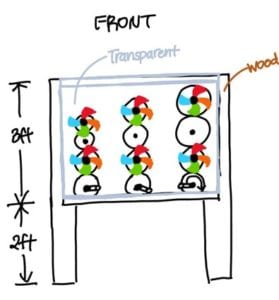
- The colorful fans were included in the design to teach children about the effect of different gear ratios not only visually but also physically.
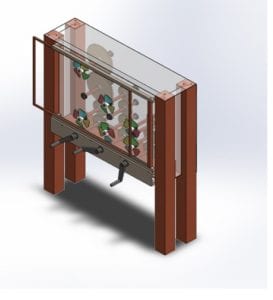
- After considering the manufacturability and maintenance of the gearbox, we have decided to modify and include additional components such as sliding display door and crank support panel to increase ease of maintenance and structural reliability. These changes were incorporated in the computer aided design (CAD) model below.
- After further consideration of safety and to simplify the physics lesson, we reduced the number of gear trains from 3 to 2. This change not only reduced the risk of injury from accidents that could occur when multiple users rotate the crank but also emphasized the speed difference of the slow and the fast gear train.
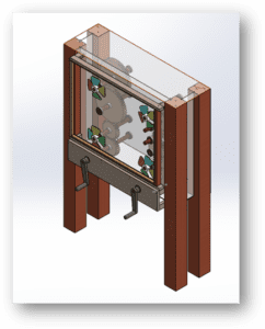
- This CAD model is the finalized model after series of Failure Modes & Effects Analysis (FMEA), Design Hazard Checklist, and Risk Assessment.

San Luis Obispo Botanical Garden
This project is sponsored by Anika Clements and Eva Vigil from San Luis Obispo Botanical Garden.
Final Design
Specifications
Weight – 224 lbs
Dimensions – 19.81″ x 39.75″ x 56.125″
Acrylic Panel was chosen for the following reasons:
- Transparency maximizes the number of users and allows observations of gear interactions from all angles.
- Top acrylic brings in natural sunlight, which helps the users to make better observations.
- The acrylic top panel protects the inside of the gearbox from rain, dirt, and leaves from trees around the garden.
Ipe Wood was chosen as the display casing material for the following reasons:
- Display casing will be completely exposed to the natural elements.
- Ipe Wood has high specific gravity, which increases durability against changing weather conditions.
Other design choices to note:
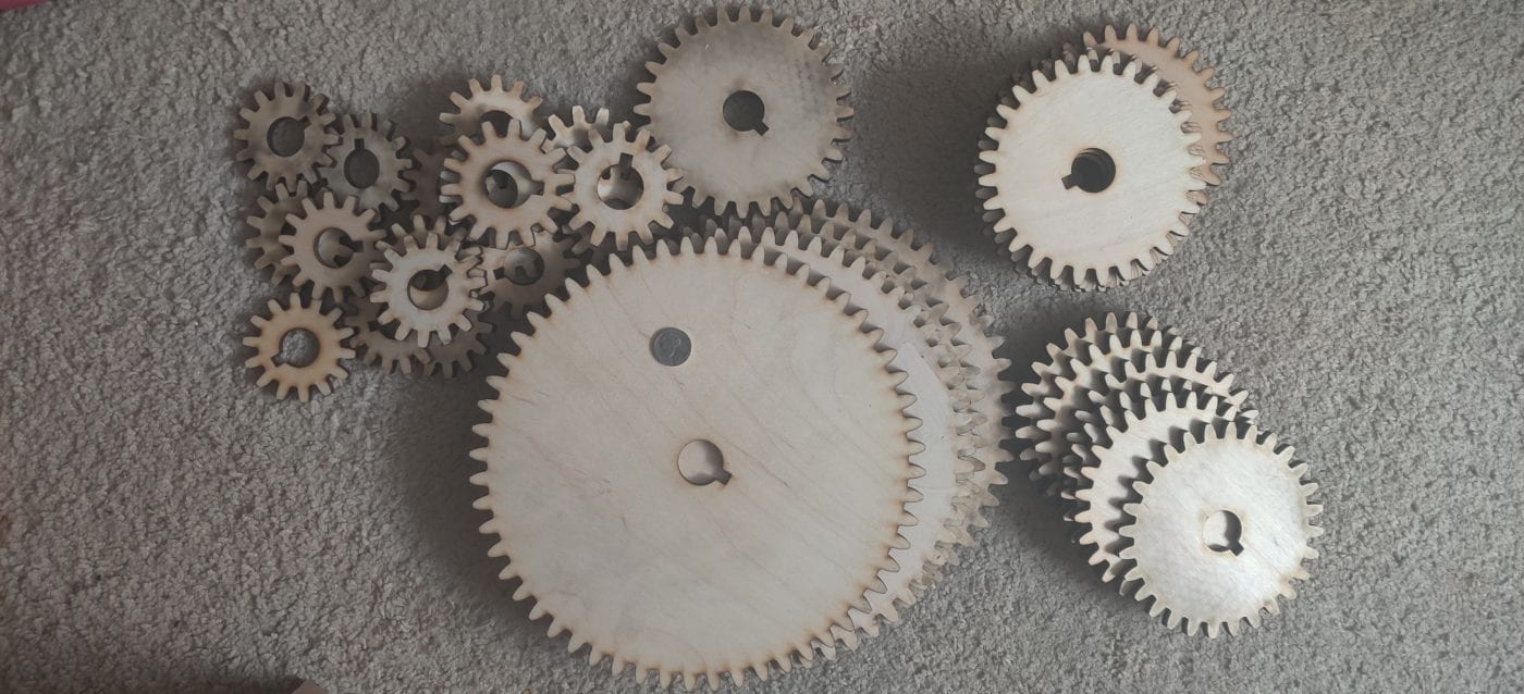
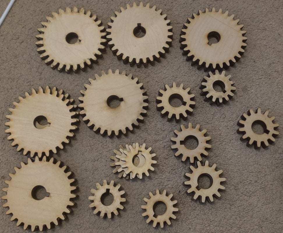
- Combining four gears of 1/4″ thickness was a conservative method of ensuring gear meshing interactions.
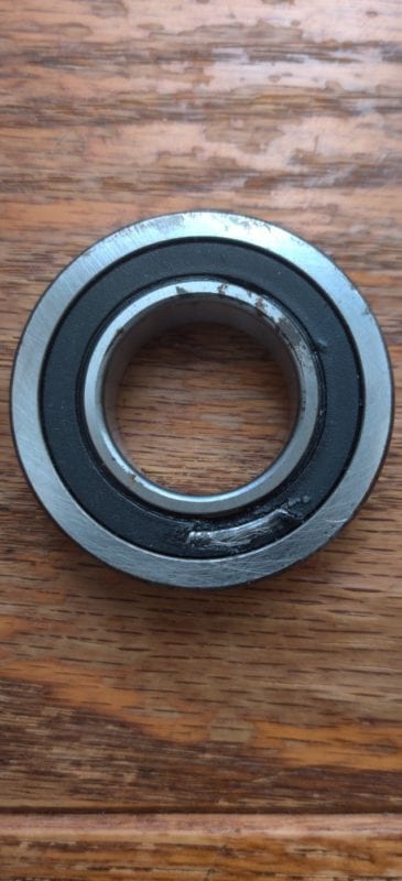
- Stainless-steel bearings were used to decrease maintenance.
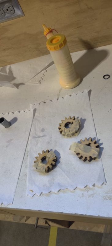
- Russian Baltic Birch was coated with Osmo Polyx-oil to further prevent dimension changes of the gears.
Testing
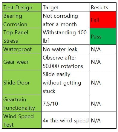
Due to the delay in our manufacturing, we weren’t able to test a lot of the test that we designed. Since the bearing corrosion test failed, we got more quality bearings that are more resistant to outdoor corrosion.
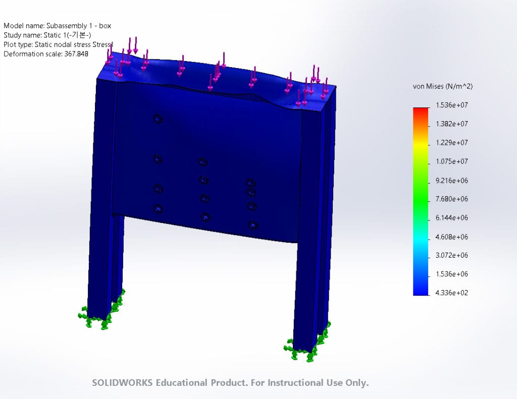
The study above is an analysis of the box in our design stage. The pressure from the above is 200 psi and the bottom surface is fixed. The deformation factor is 367, meaning that all the numbers are magnified 367 times. Looking at such a high deformation factor, we concluded that it was safe.
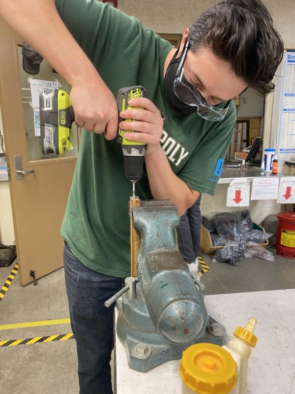
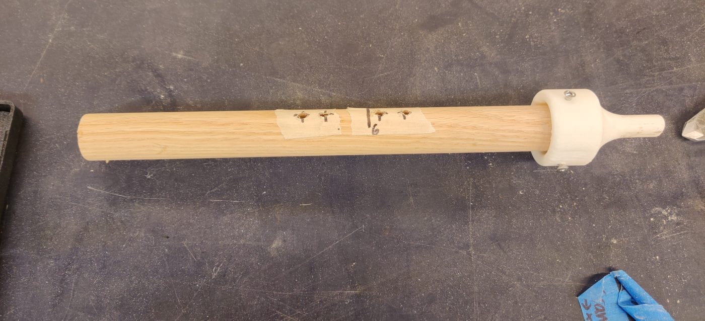
When the wooden shafts came in for our gear-train, each shaft diameter was just over 1 inch. In order to fit our bearings on, we had to sand down the shafts to reduce their diameter. After sanding down our dowels, we used calipers to measure the precise diameter of each shaft where the bearings would go. We took 5 measurements for each shaft and recorded all of the data in a table. Using the five measurements for each shaft, we calculated an average diameter for each shaft. In order for each shaft to pass, its diameter must be within 0.995±0.010 inches. We also conducted uncertainty propagation calculations for this test.
Conclusion
Recommendation to be made if the system was to be re-designed or re-manufactured:
- Find out an alternative wood for the front casing for the mesh since Ipe wood is extremely hard and difficult to manufacture.
- The front and back panel should be fully water jetted due to the easier and more precise manufacturing.
Manufacturing Process
Gearbox:
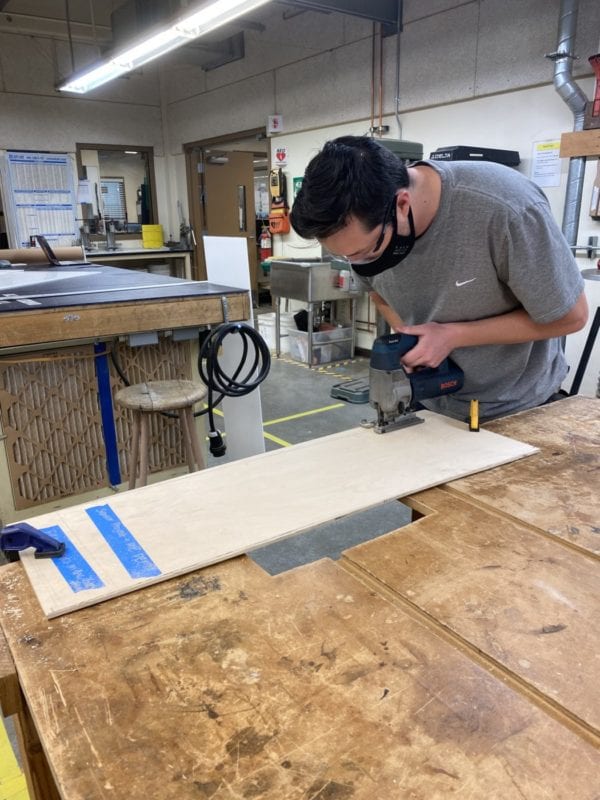
- The gearbox consists of the redwood studs and the acrylic panels. Our redwood studs came in 3.5″x3.5″x8′ stock. We cut each stud to 7 feet in length using a miter saw. We then used a table saw with 1/4″ blade height and 1/8″ blade thickness to cut the slits along the length of the studs. These slits will hold the front and side panels in place. We then used a hand router to make the small horizontal slits in the studs where the bottom acrylic panel slides in.
- Our acrylic panels are 1/4″ thick and came in 4’x4′ stock. We used a table saw to cut all of the panels to size. From there we used a circular saw drill bit to cut out the bearing holes. Then we used a dremel to make the bearing hole size more precise. Cutting the bearing holes in the back panel was a success, but we accidentally made the holes in the front panel to large. We ended up using the WaterJet in the Mustang 60 machine shop to cut a new front panel. We then used the dremel to make the holes to size.
Gear-trains:
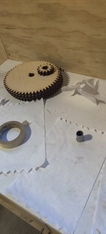
- Each geartrain consists of a dowel, gears, gear key, shaft collars, and bearings. The collars and bearings were purchased parts. Our round dowel stock was 3 feet in length and 1 inch in diameter. We used a miter saw to cut the dowels to length. Each dowel was just over 1 inch in diameter so we had to sand down the dowels for the bearings and collars to fit. We used a 3D-printed part to attach each dowel to a drill and spun the dowels in sand paper until we reached our desired diameter. Next, we used a chisel set to make a square shape on the end of the crank-rods to fit our square-bore cranks. Finally, we used a drill to drill holes where our gear keys go. Our gear keys are small wood dowels that were 1/4″ in diameter and 1″ long. We used a band saw to cut each dowel key to its appropriate length. Each gear was cut using the Laser Cutter in the Mustang 60 machine shop. We used 1/4″ hardwood stock and glued 4 pieces together to create each 1″ thick gear.
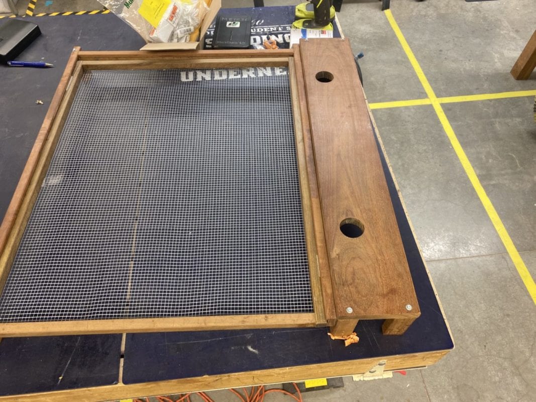
Display Case:
- The display case consists of rectangular dowels, square dowels, one rectangular panel, and hardwire cloth (mesh). The rectangular dowels and panel are made from Ipe wood. The rectangular dowels came in 1″x2″x36″ stock and the panel came in 1″x6″x36″ stock. We used the miter saw to cut both the dowels and the panel to size. We then used a circular saw drill bit to cut the bearing holes in the front rectangular panel where the crank shaft will come through. Small bits of the rectangular dowels were cut to act as supports to attach the display case to the redwood studs. Once we cut the supports, we used a power-drill to drill pilot holes. The longer pieces of rectangular dowels act as the display case frame and have slits routed in them so our mesh door can slide inside of it. We used a table router to make those slits. The rectangular dowels came in 3/4″x3/4″x36″ stock and are used to make our sliding mesh door. We used a miter saw to cut the dowels to size and then used a power drill to make pilot holes and assemble the square dowels into the shape of our doorframe. Finally, our mesh stock came in a roll 3’x10′ and consisted of 1/8″ mesh squares. We used a dremel to cut the mesh to size and then used an electric staple gun to secure the mesh to the doorframe and around the display case.