Reconfigurable Seating System for Transit Vehicles
Mechanical Engineering, Spring 2021
The reconfigurable seating system is a flexible seating solution for transit vehicles that allows operators to change the configuration of the floor plan in a timely manner in order to accommodate change in needs. This project consists of three senior project teams each working on a component of the design: system, track & latch, and articulation. Descriptions of the responsibilities of each team will be discussed below.
Table of Contents
Our Team
System Team
Daniel Turn
I am a fourth-year mechanical engineering student with a general concentration from Modesto, CA. I currently am the mechanical lead for Cal Poly PROVE and enjoy surfing, hiking, and soccer. I am interning with Northrop Grumman this summer and will be continuing my education at Cal Poly next year as a Mechanical Engineering blended Master’s student focusing on design and stress analysis.
Steven Kam
I am a fifth year mechanical engineering student with a general concentration. I am from San Marino, California and enjoy playing tennis, poker, and paintball. I have interests in design and manufacturing.
Phoebe Zeiss
I am a fourth-year mechanical engineering student with a general concentration from Roseville, California. I enjoying cooking, running, and camping. I am interested in renewable energies and hope to pursue a career in this field post-graduation.
Audrey Trejo
I am a fourth-year mechanical engineering student with a manufacturing concentration from Rocklin, California. This summer I will be interning with the project management team at Southland Industries before returning to Cal Poly next fall as a part of the Master’s in Engineering Management blended program.
Track Team
Nicholas Holman
I am a fifth-year mechanical engineering student minoring in English with a concentration in mechatronics. I am graduating in June 2021. I have an internship in San Jose with United Mechanical as a project manager intern. During my time at Cal Poly, I enjoyed playing with the Mustang Band.
Jacob Winkler
I am a fourth-year Mechanical Engineer with a concentration in Mechatronics. I am from San Clemente, California and enjoy soccer and board games. My past internships have covered a broad range of topics, from HVAC to Aerospace. My goal is to have a job relating to controls of mechanical systems or mechanical design.
Kai Quizon
I am a fourth-year Mechanical Engineer with a concentration in Mechatronics. My focuses include advanced stress analysis and the Themed Entertainment Industry. I am hoping to build off my experiences with the Disneyland Resort to build our generation’s great immersive experiences. I have already begun my Graduate Students at Cal Poly.
Alex Kuznik
I am a graduating Mechanical Engineer from Carlsbad, California. During my time at Cal Poly I’ve enjoyed playing in the Mustang Band as an alto saxophonist, and my role as a drivetrain lead on Cal Poly Racing. Following my graduation I will be starting as a Mechanical Engineer at Applied Medical.
Articulation Team
Emily Sun
Hello!
I’m a fourth-year mechanical engineering student with a general concentration
from Rancho Palos Verdes, California. I’m currently interning at SpaceX on the
dragon structures team and will be working on ventilator R&D for Medtronic
this upcoming summer. I hope to pursue a career centered around product design
post grad.
Anil Singh
Hi! I’m a fourth-year student at Cal Poly SLO pursuing my B.S. in Mechanical Engineering with a concentration in Mechatronics. I am from San Diego, California, and have prior research experience in the Experimental Mechanics Laboratory at San Diego State University, where I recently co-authored my first publication. I hope to pursue a career centered around product design or stress analysis post grad.
Rick Hall
I’m a fourth-year mechanical engineering major from Georgetown, California. I work in the Cal Poly machine shops as a Shop Technician, teaching other students machining skills. I’m involved in a number of railroad historical preservation organizations. My area of focus is machine design.
Acknowledgements
We would like to thank our sponsors, Dr. Joseph Mello and Ritch Hollingsworth, for their continued support and guidance throughout this project, as well as our advisor, Sarah Harding, for her dedication and assistance this year. We would also like to give a big thank you to Ted Claghorn, SLO Transit, and San Luis Obispo Regional Transit Authority for their commitment to the success of this project, as well as the Mustang 60’ and Aero Hangar machine shops for their time, resources, and expertise in manufacturing this project. Finally, we would like to thank the university, Cal Poly SLO, and the mechanical engineering department for presenting us with the opportunity to design and create this project.
Project Videos
The system team’s video is a general overview of the project. Further details about the design of the articulation and track & latch subsystems are covered in their respective videos.
Project Introduction
Problem Statement
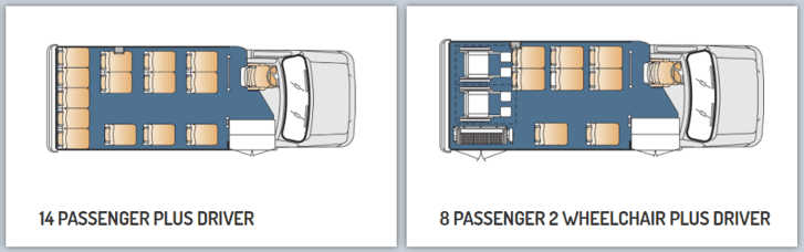
In traditional shuttle busses, seats remain in stationary positions which limits the use of the space. Shown below is an example of a shuttle bus currently on the market and two of the fixed configurations available to purchase. These configurations are fixed, so a company would have to buy multiple buses with various configurations to anticipate customer needs.
Example of a standard transit shuttle bus configuration
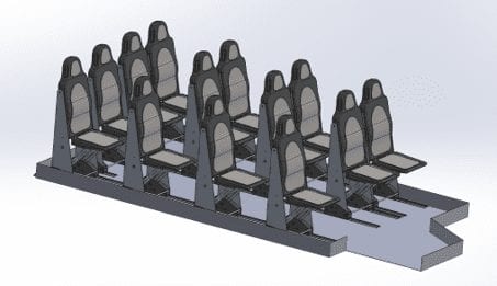
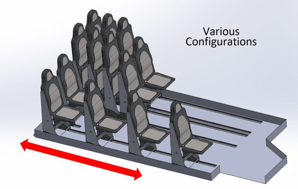
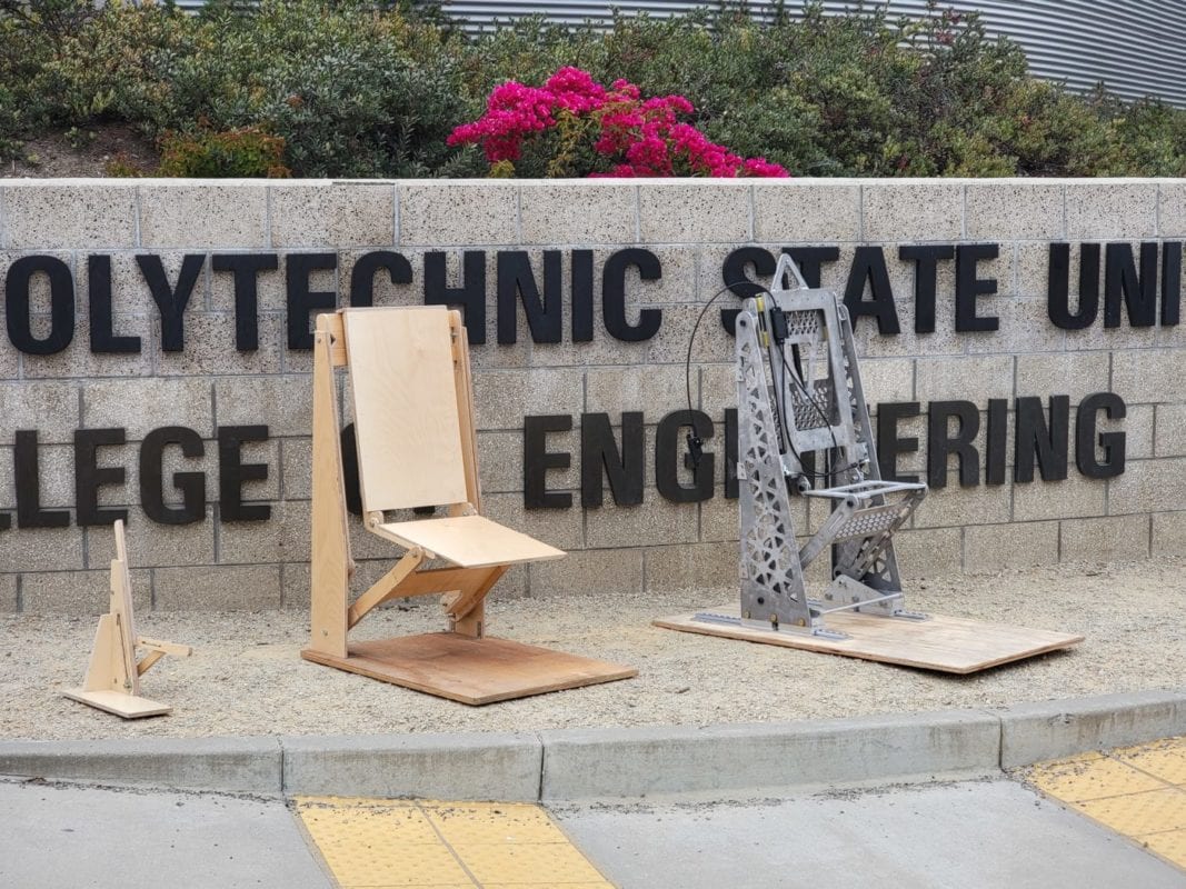
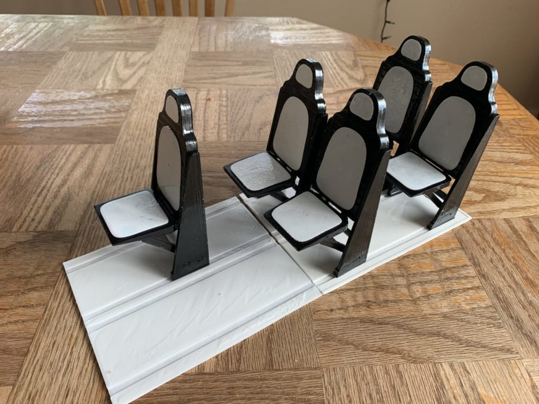
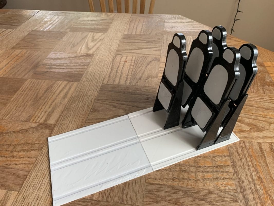
Our seating system makes it possible to efficiently change a vehicle’s configuration to adapt to riders’ needs by adjusting seats to a stowed position and nesting them together, enabling a single vehicle to house multiple seating arrangements. The pictures below are two examples of possible configurations utilizing this system.
Fully deployed configuration
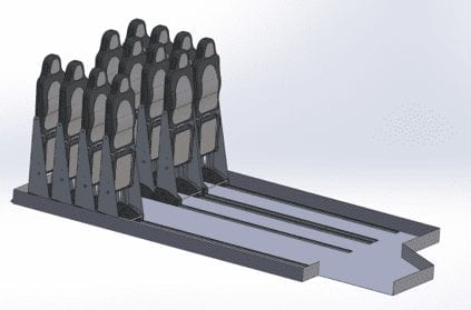
Fully nested configuration
These layout changes can be made to accommodate for more passengers, personal belongings, or passengers in wheelchairs, providing an efficient, economical, and accessible riding experience.
Background
This project was inspired by 2 past senior projects both of which were sponsored by Dr. Joseph Mello and Ritch Hollingsworth. The first team in 2015 focused on designing a similar system made for rail travel and the second team in 2018 focused on adapting this concept to buses. These Senior projects resulted in the patent US10596934B2 in 2020 which forms the basis for this system design. The current project is aimed at testing and refining a prototype system which could lead to piloting this concept in a shuttle.
Constraints
The table below shows the design constraints we aimed to hit based on our customers wants and needs. Our final prototype was tested to ensure these specifications are met.
Organization
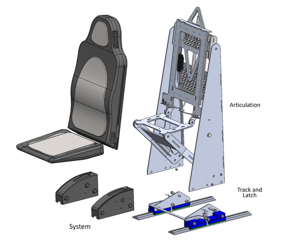
This project was split between three project teams: System, Articulation, and Track and Latch. The responsibilities for each team are as follows:
– System –
Oversee the aesthetics and integration of all teams’ components, while focusing on the marketability and direct application of the product.
– Articulation –
Define the seat’s stowing movement which allows the seat to be folded into a compact configuration to save space
– Track and Latch –
Define the seat’s nesting movement which allows the seat to be moved throughout the vehicle and locked into place
Components designed by each team
Final Design
System Overview
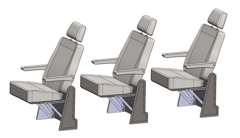
Stowing Motion
The main motions of the design are stowing and nesting. They allow for the seats to transition between multiple vehicle configurations quickly and easily. This allows various seating layouts and for a maximum space savings of approximately 65%. Videos of both the nesting and stowing motions are shown in the system team’s video.
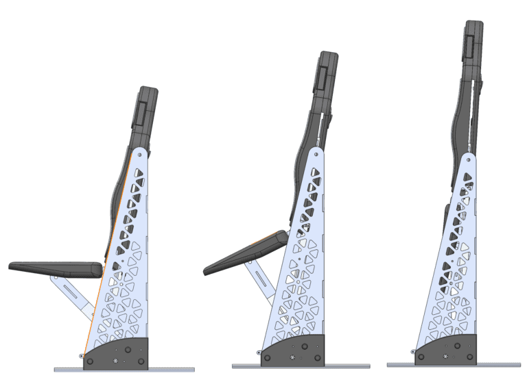
Stowing Seat – Articulation Subsystem
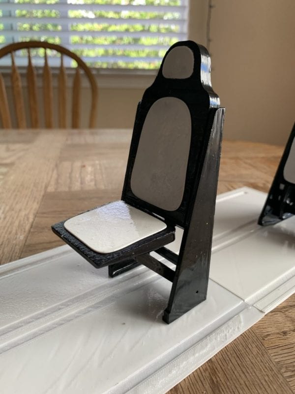
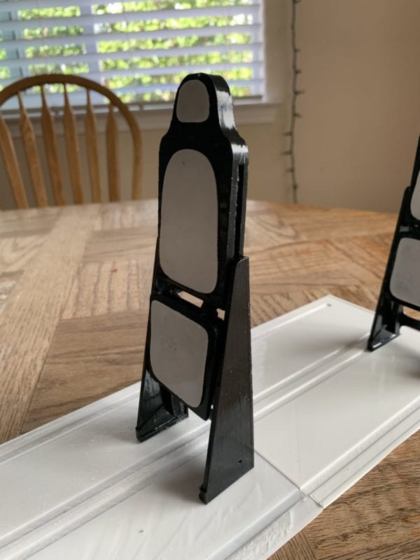
1. To stow seat, pull on the latch on the back to allow for articulation into the vertical position.
2. The seat will automatically fold up into the vertical position as shown in the picture on the right.
3. To redeploy the seat, push the seat down until it locks.
Stowing motion
Nesting Motion
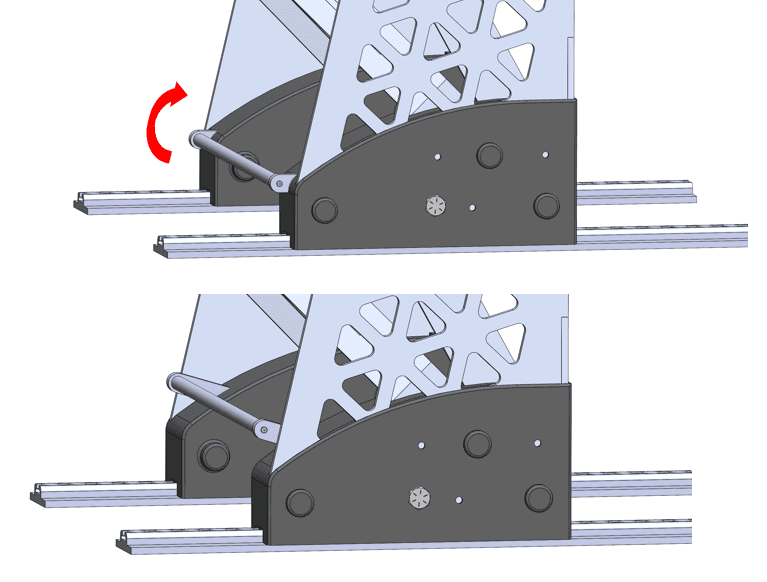
Nesting Seats – Track and Latch Subsystem
1. The driver unlocks the seat by pushing up on the foot pedal until it locks in this upright position as seen on the right.
2. Now they can move the seat back and forth along the track to various configurations as seen in the image below.
3. When in the desired layout, the driver pushes down on the foot pedal to lock the seat back into place.
Unlocking the seat for nesting
An example of a possible configuration
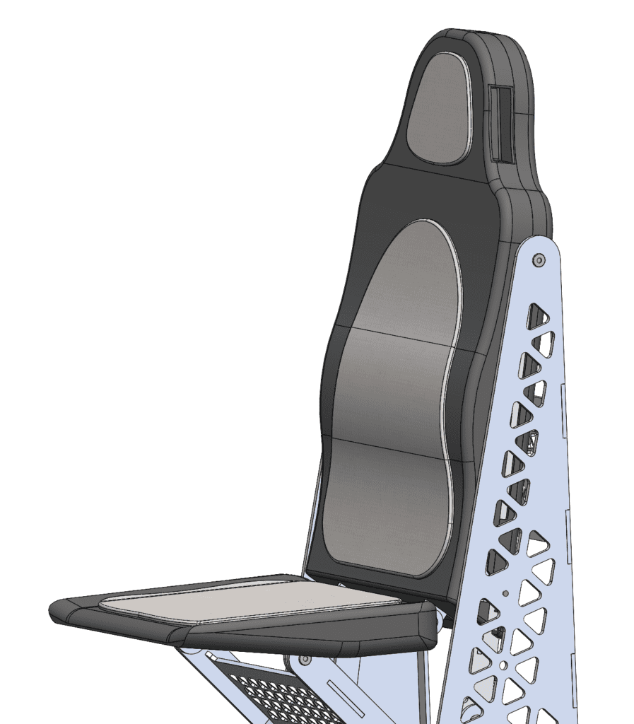
Aesthetics and Ergonomics
User safety and comfort were an important part of making the product marketable, which is why we wanted to make our design aesthetic, safe, and ergonomic. This was at the forefront of designing the seat itself and during integration of the three subsystems together.
This was achieved by housing a majority of the articulation and track components within plastic housing to minimize pinch points and improve aesthetics.
The plastic molded seat back and bottom are also designed with ergonomic contours and padded with a light cushion.
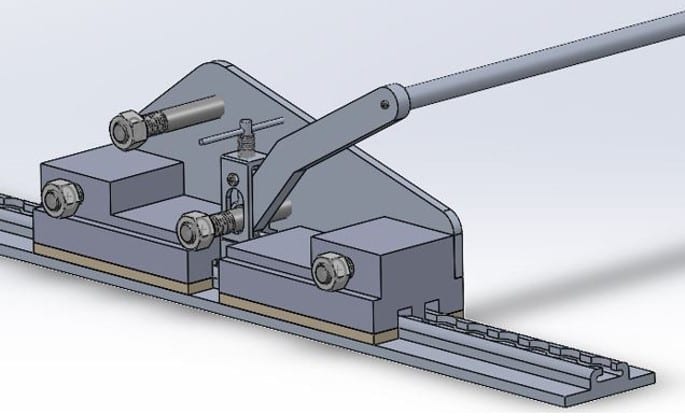
Track and Latch Subsystem
The Track and Latch subsystem is designed to toggle between two modes: fully constrained and one degree of freedom motion. It is desired to quickly and securely toggle between these two modes with a single user input. As such, the track and latch system consists of the track, latches, and an cam based actuation system. The track provides the grounding point for both vertical containment of the unit and horizontal containment when engaged. The latches have a profile that matches the track, allowing for the latches to slide along the track but not disengage vertically. The actuation system controls a locking pin, which mates with the track when locked and prevents horizontal motion. As a unit, the system only allows travel along the track when unlocked, and is completely constrained when locked.
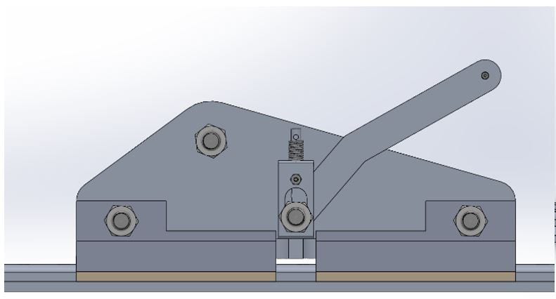
Finalized CAD rendering of one side of the track and latch subsystem. The system is mirrored across the articulation system for two connection points
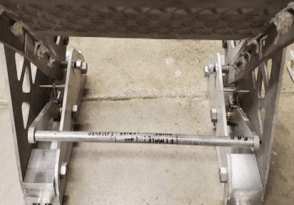
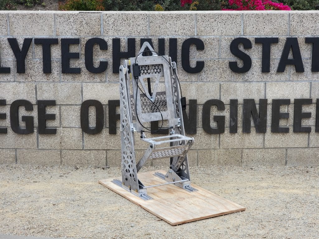
Final Verification prototype, focusing on track and latch subsystem. Mirrored instances on both sides connected via the actuation bar. This actuation bar acts as the user input to the system.
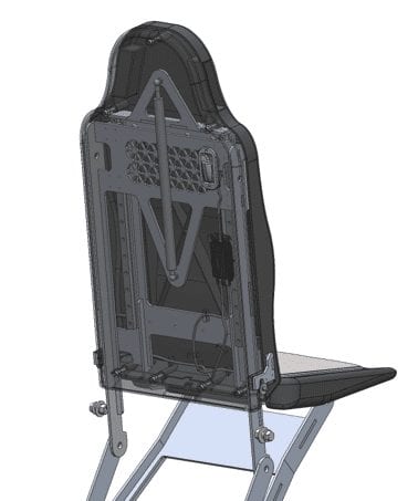
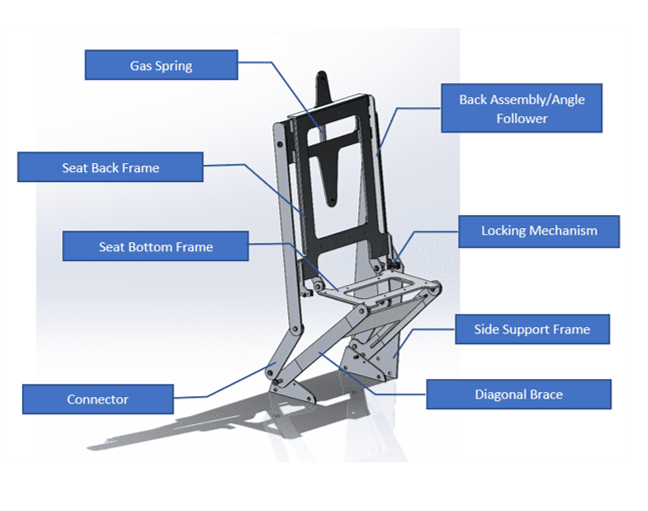
Articulation Subsystem
The articulation subsystem consists of two conjoined four-bar linkages; the rear rocker-rocker linkage to control the angle and the front rocker-slider to control the seat elevation. By pressing on the shoulders of the seat, the seat may be deployed. A gas spring allows the seat to be stowed simply by pulling a release lever. By locking the seat back with the rotary latches the rear linkage is isolated and the seat assembly becomes rigid.
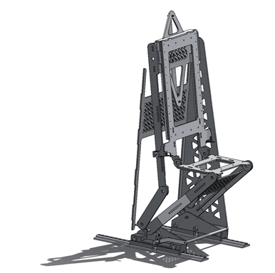
Simplified CAD rendering of articulation subsystem.
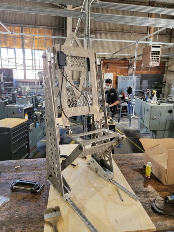
Final verification prototype, focusing on articulation subsystem.
Design Process
The current design was the result of multiple iterations through three quarters of refinement. The following section details this iteration process for each team, illustrating how we arrived at our final design.
System
Before selecting our final design, we had several initial seat iterations, one of which is shown in the picture on the right. This design was based on a typical sprinter van seat. The seat was designed to be made from foam and covered in fabric. Although it did have skirts around the outside, the articulation components were more visible and left many more pinch points accessible.
Initial system ideation
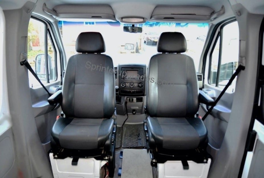
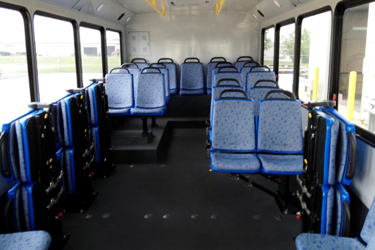
After this initial iteration, we changed the vehicle type we were designing for to be a shuttle bus which has a much different interior as shown in the comparison below. We iterated our design to reflect this change by switching to plastic and simplifying the seat so that it is easy to clean, light weight, and allows the articulation components to be housed inside which reduces access to pinch points. We converged on our current design to be more aligned with shuttle bus seats and to minimize costs while still having an aesthetic and ergonomic design.
Typical sprinter van interior and seats
Typical shuttle bus interior and seats
Overall we chose our current design for the following reasons:
– Ergonomic and aesthetic while still being cost-effective
– Plastic chosen to be easy to clean and to reduce manufacturing costs
– Plastic shell allows articulation components to be housed inside
– Comparable to seats in similar vehicle types
Track and Latch
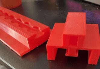
We began our design process with a series of low resolution prototypes to flush out various concepts for our functions. These low resolution prototypes allowed us to work in physical space and test new ideas quickly without high time or materials investment.
3-D printed model of track and latch
3-D printed CAM lever arm
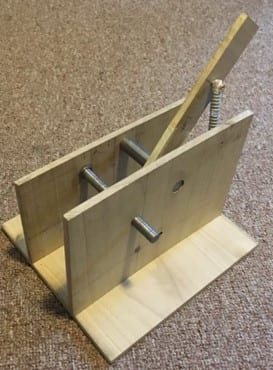
After refining our ideas to a few key components and concepts, we utilized rapid prototyping processes to check our designs at full scale. This allowed us to evaluate any interference between the carefully design mating profiles and also visualize key components at scale prior to manufacturing.
Wooden prototype to test initial locking system
A full scale, structural prototype of version one of our actuation system was completed next. This structural prototype proved integral in determining the safety of this system. After working with this prototype at full scale and full materials for integral components, we determined that the first iteration of the actuation system was insufficient to meet the design parameters of one user input while still securely locking in place. Using this material, we redesigned to the cam actuated system used in the final design.
Articulation
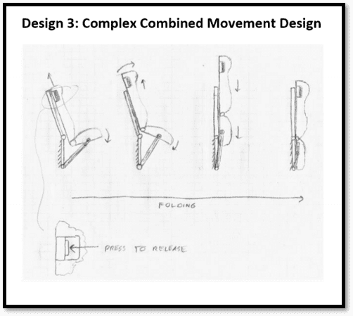
Initial design concept: Design 3 (seen below) was our initial chosen design direction during PDR. This design included an additional downwards motion at the end of its articulation path to save vertical space.
Prototype of Design 3
Initial ideation of Design 3
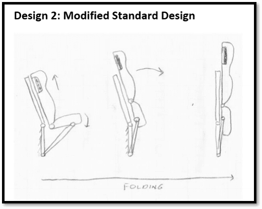
Post-PDR discussion led us to execute on Design 2 (seen below) instead because it allowed for the same horizontal space saved while eliminating complex linkage elements, primarily the need for slots.
Prototype of Design 2
Initial ideation of Design 2
Reasons for current seat design selection:
– Vertical stowed position maximizes space saved when seats are pushed together
– Simple single user input to deploy the seat into is seated position
– Gas Spring automatically stows seat when latch is released
– System of linkages allow for a more ergonomic seat back tilt in its deployed state while preserving the perfectly vertical stowed state
Analysis
Preliminary analysis on our proposed design was crucial in ensuring the design would pass FMVSS loading conditions, and remain functional to an operator. The following section outlines the analysis performed by each team before manufacturing a verification prototype.
System
Overall system analysis focused on two primary aspects. One was ensuring that the plastic seat would meet the strength and stiffness specifications required by our constraints and the other being making sure that a seat belt would be adequate if a crash were to happen and if the vehicle requires a seat belt. Summaries of the results of both of these are below.
Seat Material Analysis:
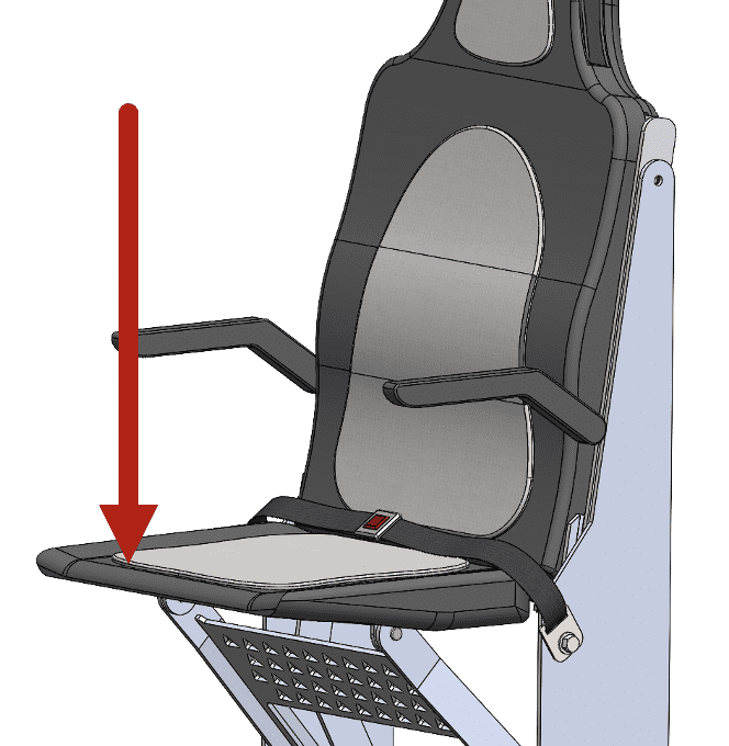
It was also important that the seat would not fail under heavy loads. To maintain a high factor of safety, we chose a force of 600 lb to be applied downwards at the end of the seat. Simplifying the seat as a hollow, cantilever beam, we found that the stress experienced by the seat is lower than the yield strength of polyethylene and the vertical tip displacement is within our design constraints.
Vertical force for tip displacement calculations
Seat Belt Analysis:
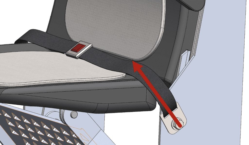
Basic calculations were performed to confirm that the seat base and seat belt placement were adequate in the event of a crash. Using a simplification of 20 times the weight of the passenger to model the force of the crash, we found that the stress experienced by the base from the seat belt during a crash is much lower than the yield stress of steel.
Force on seat belt for crash calculations
Track and Latch
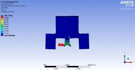
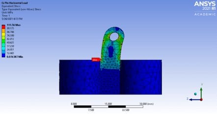
We identified three critical components within the track and latch subsystem whose failure would result in system failure and potential injury. These components include the latch (below left), the double pin (below right), and the track (not pictured). Each of these components was analyzed using traditional methods. When the traditional methods were fully developed, finite element analyses were conducted. Convergence was achieved with both the hand calculations and the mesh study. This allowed for the placement of stress reliefs in the form of chamfers and fillets. Ultimately, these changes resulted in a minimum yield safety factor of 1.89 and a minimum deflection clearance of 0.05 inches. These results gave us the confidence necessary to begin manufacturing.
FEA results for Latch
FEA results on locking double pin
Articulation
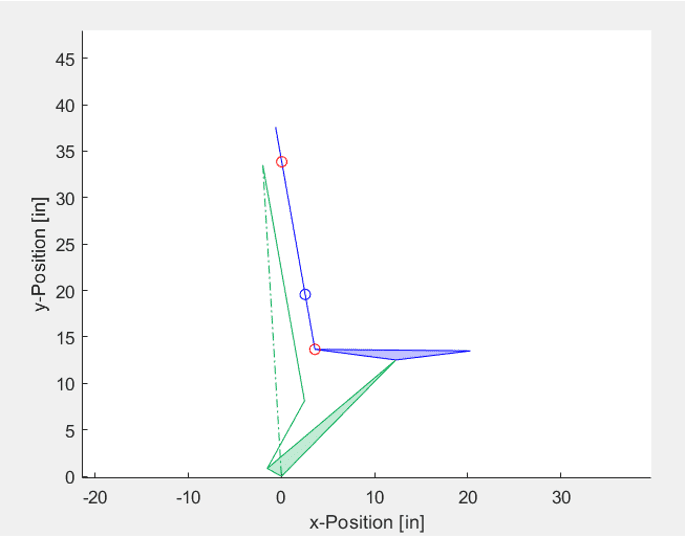
Graphical linkage synthesis was used to develop the basic concept (refined as the Solidworks sketch shown below). Analytical linkage synthesis methods were used to optimize the linkage geometry and compute pin loads (iterated and animated in MatLab). Hand calculations (iterated via MatLab) and FEA analysis were conducted to ensure the stresses in the linkages were below our allowable for all driving load cases with a safety factor of 2.0. Bearing calculations were also done for our pin joints to ensure that they would not fail in shear.
MATLab kinematic analysis simulation
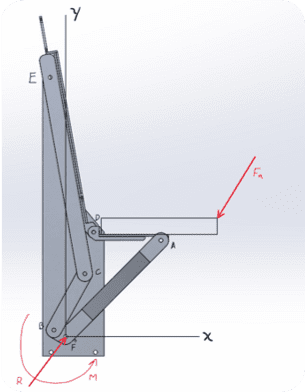
Free body diagram of one possible in plane loading condition on seat
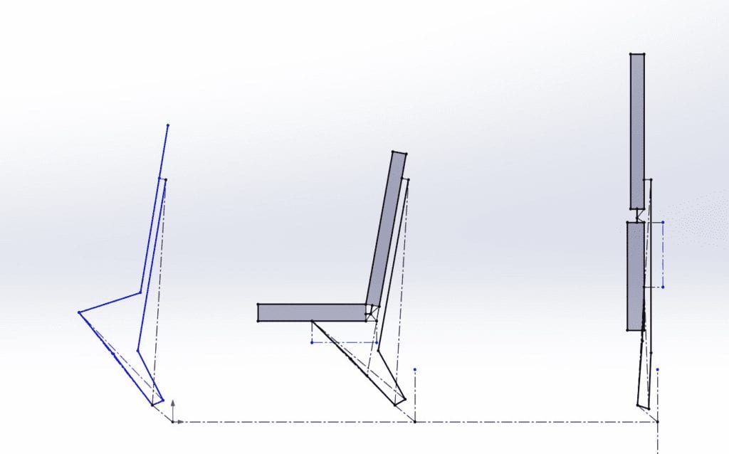
Graphical linkage synthesis performed in SolidWorks
Manufacturing
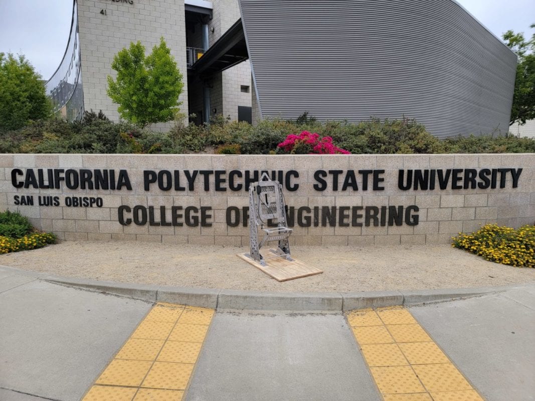
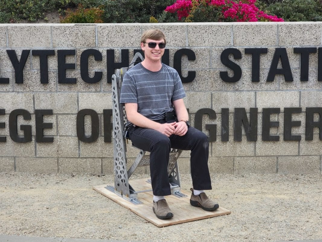
After refining the concept for the seating system, as well as after performing preliminary analysis, a verification prototype could be constructed to physically asses the versatility of the design in a physical landscape. The section below outlines the manufacturing procedures performed by the track & latch team and articulation team in constructing a verification prototype sub assemblies. The components of each team were then integrated to form our final verification prototype. Instead of manufacturing, the system team completed a grant proposal for the IDEA program and 3D printed a model of the seating system at 1/8 scale. More information about the grant proposal can be found in the Future Development section and pictures of the 3D printed model are located in the photo gallery.
Track and Latch
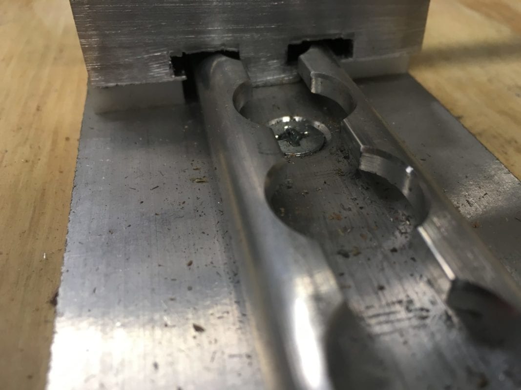
Our final product was made from Aluminum and Delrin. Manufacturing was broken down into three subsystems: Latch assembly, CAM assembly, and the track. The latch was the most time intensive process that involved milling and drilling. The CAM assembly was created via the water jet in Mustang 60, and a few more cuts on the band saw. The table below explains the material and processes used. All three systems were combined to create our final product.
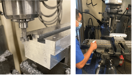
Left: T-slot end mill to create Latch profile. Right: Spraying coolant to ensure clean cut
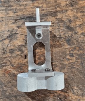
CAM follower sub-assembly
Articulation
The articulation team was responsible for manufacturing all components of the seat frame component for the verification prototype, except the track and latch portion which was later integrated. The general process for manufacturing the verification prototype fell into three phases: Cutting the stock ¼” aluminum plate on the waterjet to the appropriate geometry, welding each component as well as performing any post processing operations to create sub assemblies, and assembling the subassemblies and outsourced components into a final product. The table below details these phases in detail, and the illustrations show key steps of these phases.
Tapping threads for rail attachment on seat back sub assembly
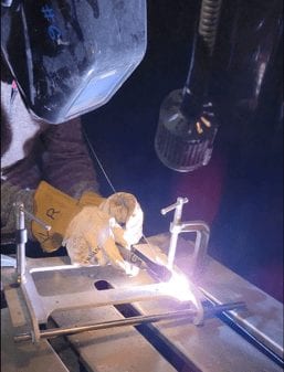
Rick welding together seat bottom sub assembly
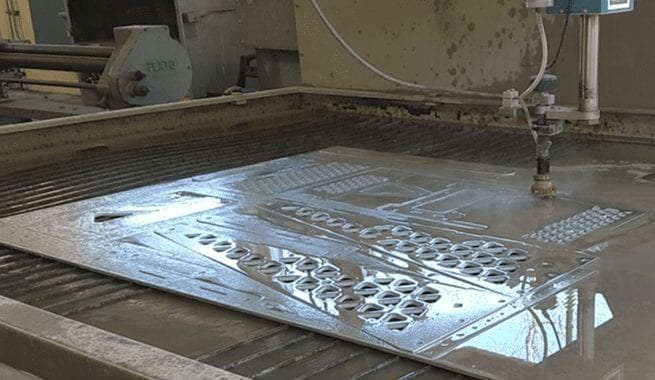
Waterjet cutting operation being performed on stock 1/4" aluminum
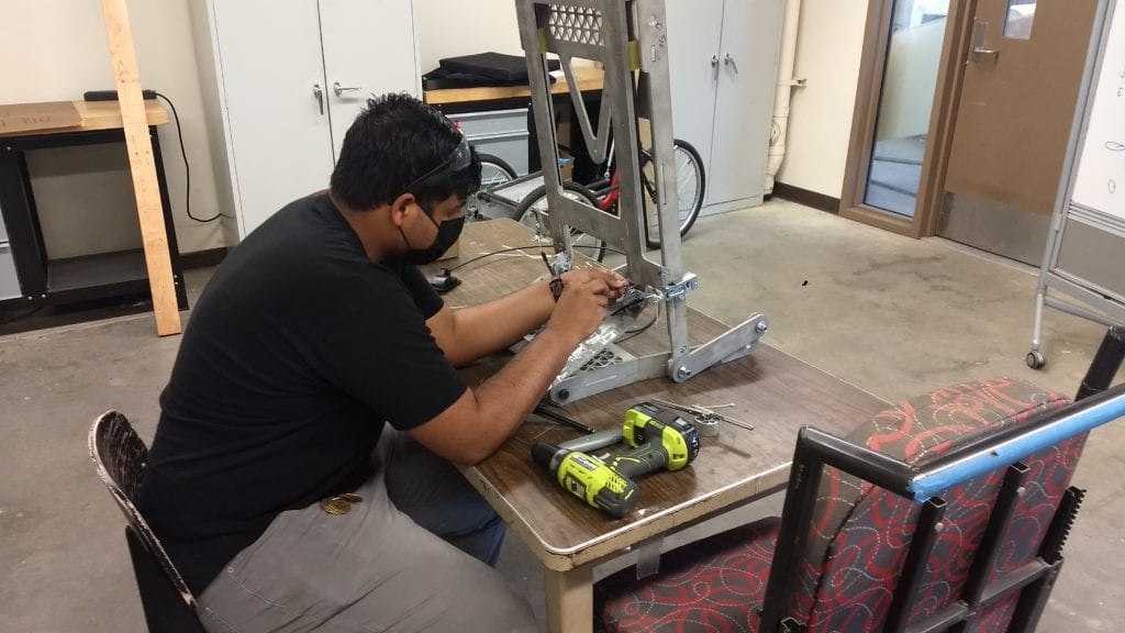
Anil assembling subassemblies and outsourced components into final verification prototype
Testing
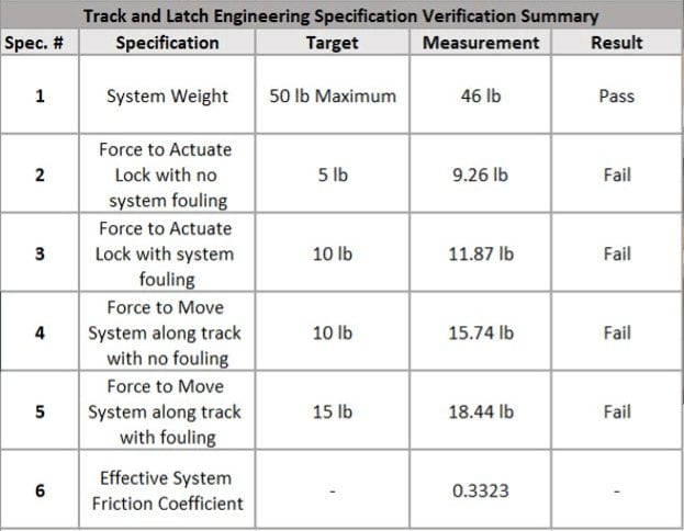
The purpose of manufacturing a verification prototype was to verify that the proposed design meets all engineering and design specifications in a manner that is directly observed in a controlled environment instead of in a simulated or modelled environment. As such, the design and performance of physical testing on the verification prototype was necessary to achieve this goal. This section outlines the details and procedures used in each test, as well as the results and analysis that prove that the proposed design meets all engineering and design specifications.
Track and Latch
We performed four critical tests to verify our system parameters. We measured the force to actuate the front bar to lock and unlock the seat. We also measured the force required to slide the seat along the track. Both these tests were performed under clean and dirty conditions. We simulated the dirty conditions by introducing dirt and grim on the track. The results of all these tests are shown below.
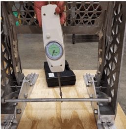
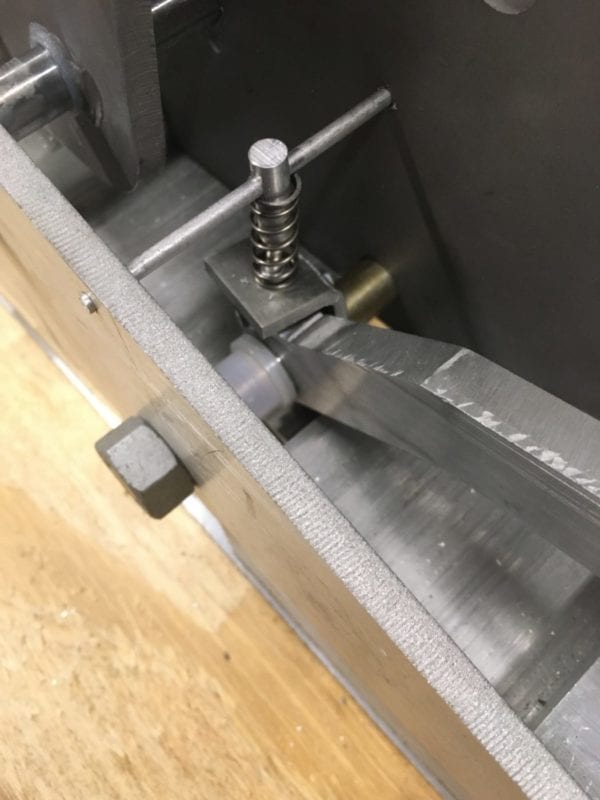
Measuring the actuation force to lock the seat in place
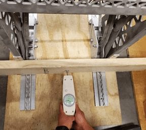
Measuring the force required to slide the seat along the track
Articulation
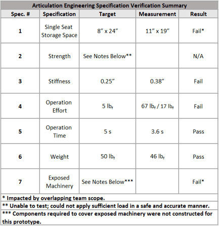
For the articulation team, our primary goals with testing performed on the verification prototype were to quantify and measure deflection, effort, and time data in such an environment. Although we performed 5 tests in total (of which all results can be seen below) these three quantifications led to the most insightful conclusions, as discussed later.
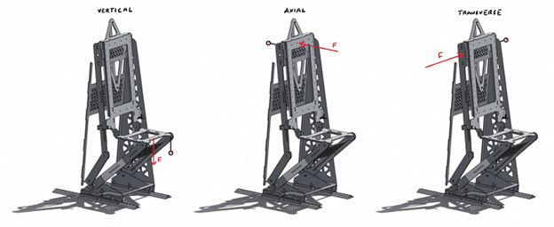
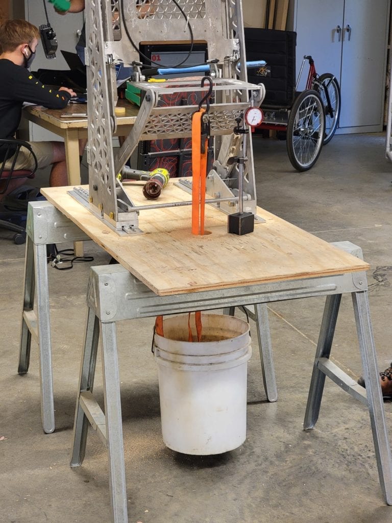
The deflection test consisted of loading the seat in various orientations and measuring the corresponding deflection with a dial indicator. Vertical, axial, and transverse loading conditions on the seat were measured, with weighted buckets and ratchet straps providing a load in the vertical directions, and a manually applied force (using a force gauge for accuracy) providing a load in the transverse and axial directions.
Types of forces tested to measure deflection
Deflection test (vertical loading condition)
Deflection test (horizontal loading condition)
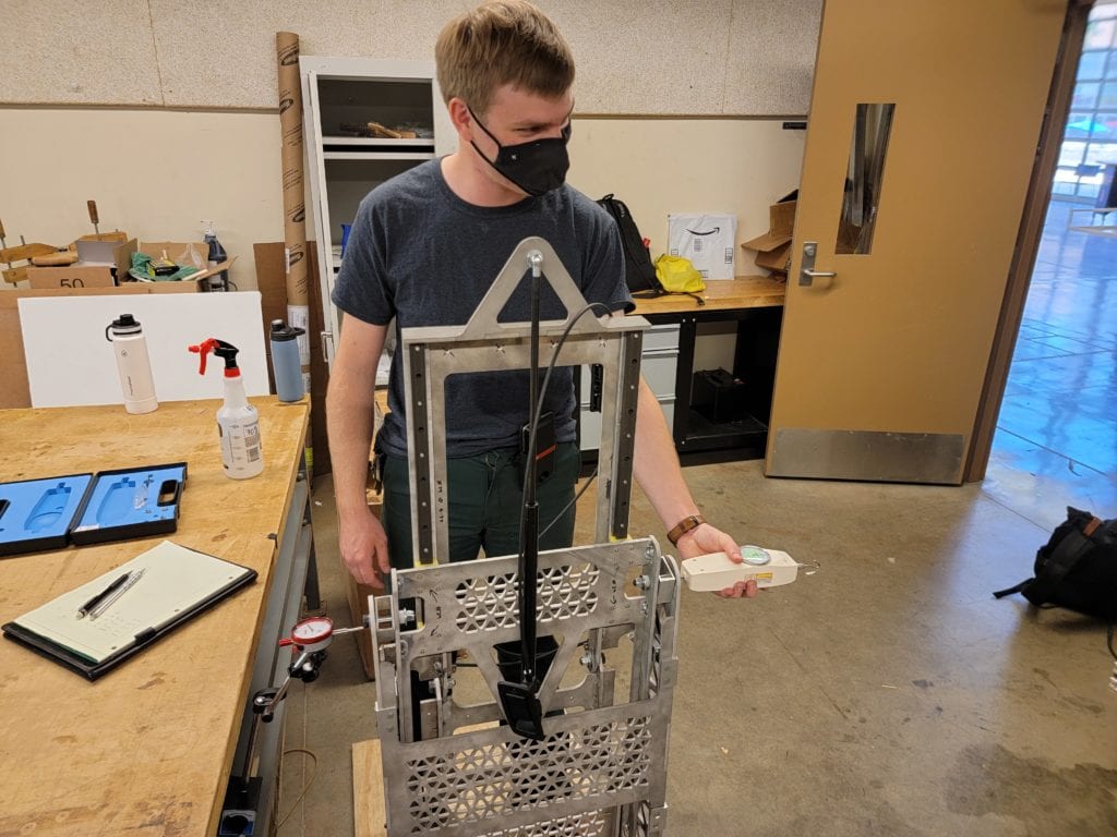
The operation effort test was performed to measure the amount of force needed by a user to operate the seat. Two different conditions were considered: moving the seat against the gas spring from a stowed to a deployed configuration, and moving the seat from a deployed back to a stowed configuration with the gas spring disconnected from the system.
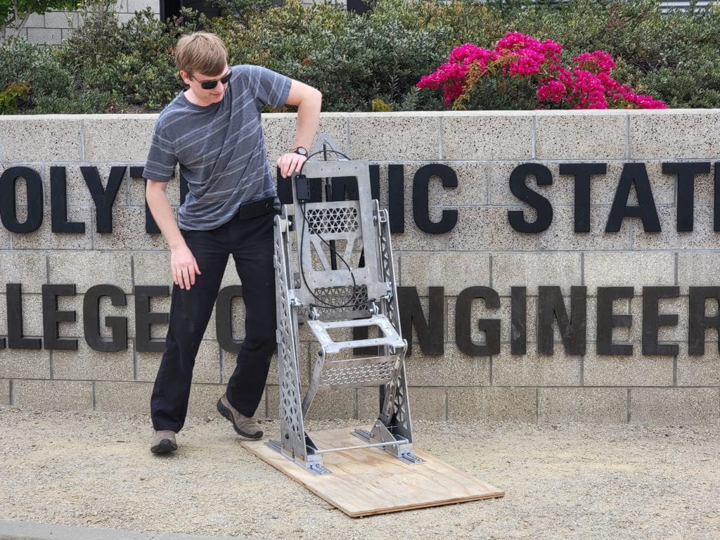
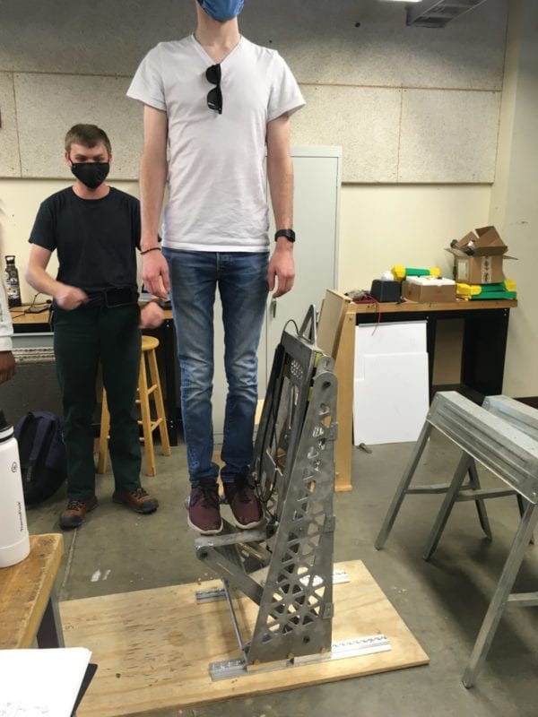
The operation time test was conducted to gauge the intuitiveness and ease of use of our final design. The scope of this test included timing how long it took a testing participant to stow and deploy the seat.
Operation time test
Future Development
The following section outlines the future applications we see for this project, as well as recommendations we have based on the design, manufacturing, and testing of our verification prototype that could be implemented in another iteration of this project.
Future Application
In May, we submitted a proposal in hopes of receiving a Transit IDEA grant which would fund a new undergraduate research team to further explore this concept next year. This grant would provide the resources to iterate the current design, produce multiple full-scale prototypes, and do in-depth structural and user testing to finalize this system design. Throughout this process, we gained support from the City of San Luis Obispo as well as the SLO Regional Transit Authority. Both of these organizations expressed interest in the concept of configurable seating and have agreed to help improve the design if we were to receive the grant. This system has the possibility of improving vehicles in both the public and private sectors.
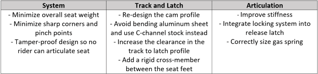
Recommendations
The system team talked to the local transit agencies SLO Transit and RTA to gain insight on how our design can be improved. The articulation and track & latch teams concluded on additional recommendations based on their testing and manufacturing processes. The table below summarizes each team’s recommendations.
Send an email to pschuste@calpoly.edu to be connected with the project team. Please include the title of the senior project you’re inquiring about in the subject line.
Interested in Sponsoring a Mechanical Engineering Senior Project?


![received_315161136183083 (2)[44]](https://projectexpo.calpoly.edu/wp-content/uploads/elementor/thumbs/received_315161136183083-244-p8obihsid5ts9m6opbh0aiclaiws52myt4yb7w8cas.jpg "received_315161136183083 (2)[44]")


