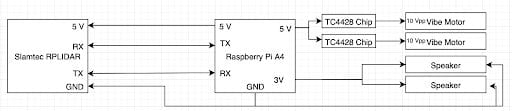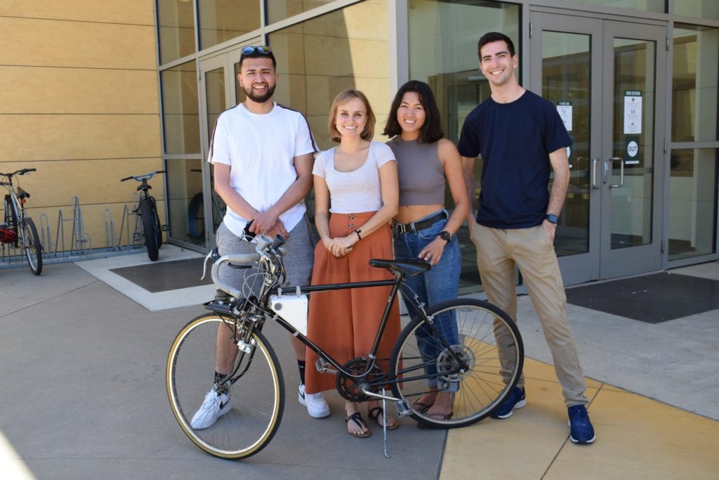

Zoe Lam
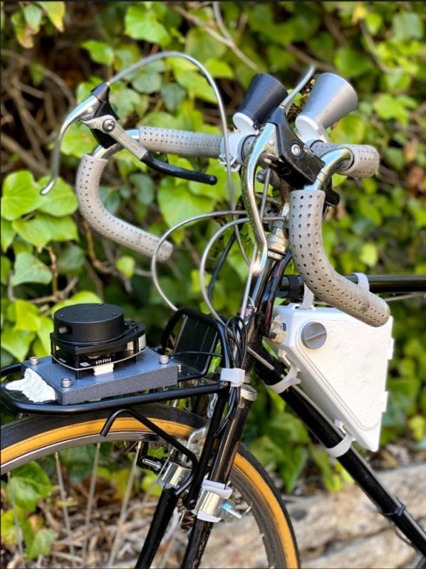
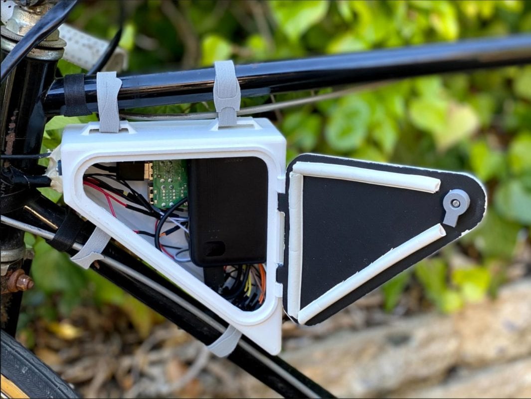
Mechanical Engineer

Balthazar Olivier
Manufacturing Engineer
Astrid Jouret
Industrial Engineer

Javier Flores
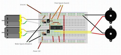
Electrical Engineer
This project is sponsored by TECHE and Cal Poly QL+