Snobot

Unmanned Ground Vehicle for Domestic Snow Removal

Our Team

The Snobot Team consists of five members from Cal Poly SLO’s college of engineering.

Nathan Piantanida

Electronic Manufacturing Lead

I am excited to graduate this June with a BS in Mechanical Engineering and a concentration in Manufacturing. The idea to build this marvel of embedded systems struck me one day as I laboriously shoveled snow to clear my driveway in Colorado. When our sponsor Bruce proposed his ambitious idea this fall, I had purpose to pursue that calling. The Snobot project to me represents what is possible when Cal Poly Engineering is dialed to the max.  My responsibility for this project was robot localization, autonomous control, electronics manufacturing, system prototyping, and team cohesion. The smoke of burnt electronics, faulty code, and integration growing pains taught us about mechatronics, mobile robotics, systems design, autonomous perception/localization, and teamwork. I intend on furthering the development of this project after my graduation from Cal Poly.

William Dorosk

Mechanical Hardware

I am a fourth-year engineering student at Cal Poly, San Luis Obispo. I will be graduating in the Fall of 2021. This project has expanded my knowledge on electronics and autonomous hardware like Pixhawk. The Snobot taught me a lot about stereovision and camera systems. 

David Riegel

Custom Part manufacturing lead

I am a fourth-year Industrial Engineering student at Cal Poly, San Luis Obispo graduating this June,   2021. I’ve had a previous internship with my home-town brewery, South Lake Brewing Company (SLBC) where I implemented a QR code tracking system for their keg inventory. After graduation, I will be returning to work with SLBC over the summer. This project has expanded my knowledge of electronic systems, and has allowed me to demonstrate my solid modeling skills.

Steven Zhu

Electrical Design Lead

I am an Electrical Engineering Student from Cal Poly San Luis Obispo graduating in June 2021. After working on this project, I have learned a lot about integrating autonomous and mechanical systems. I have gained many valuable skills such as teamwork and problem solving. I believe that autonomous machines are the key to the future and believe this project will improve the lives of many homeowners.

Kira Hebbel

Modular design, human machine interaction

I am majoring in general engineering with a focus in product design, and am minoring in computational interactive art, a study combining both computer programming and digital art. While art and engineering may seem to oppose one another, there is an important point of overlap and I strive to be the facilitator in their fusion. Completing this interdisciplinary senior project, I have learned a variety of skills from mechatronics and autonomous systems to mechanical design and testing. This project allowed me to bring together a multitude of my skills and enhance my ability to approach product development as a concurrent and integrated process.

Acknowledgements

We would like to give special thanks to our sponsor, Bruce Burnworth, and our advisor, Vladimir Prodanov for his guidance on our project. Special thanks to Ryan from Spyker Workshop for contributing his custom prototype and willingness to work with us. Furthermore, we would also like to thank Jim Widmann and Karla Carichner for their pertinent council.


Our Project's Videos

Testing conducted outside Building 41 – Engineering IV at Cal Poly

Our Project's Digital Poster

Objective

The goal of the project is to provide an autonomous snow blower solution (SnoBot) to Bruce Burnworth, that will pave his pathway from his garage, to his home, in Lake Tahoe.  The SnoBot is to perform without any form of human intervention through operation and charging. 

Overall Cost

DescriptionPrice
Spyker 3D KAT and Snowblower$8,200
Automation (Sensors, Microcontrollers, etc) $931.43
Total$9,131.43


Electronic Hardware

  • The Pixhawk 4 is an open-source autopilot system tailored to autonomous aircrafts. By adapting the Pixhawk to Ground Rovers, we are able to create an autonomous machine. Through Pixhawk, we are able to create waypoints using it’s on-board GPS module to guide the robot’s location through any location.
  • To create a more accurate navigation system, we use RTK GPS to increase the accuracy of the Snobot. RTK GPS positioning works by having a base station to take its measurements from surrounding satellites to relay its data to the rover. To further improve the accuracy of RTK GPS, we will be using RTK as a source of correctional data to further improve its accuracy to 10 cm.

  • Since the rover would be in the snow,  we will be using  9 waterproof ultrasonic sensors. These sensors will be attached in front of the robot in a semi circle to have a full coverage with no gaps. An advantage of ultrasonic sensors are the ability to detect objects in-front of it which should not be affected by falling snow.
  • There is a problem with vibrations affecting the sensors, as a result, we attached a boom to the body of the robot to minimize the vibrations the sensors may face.
  •  
  • Due to the ultrasonic sensor’s inability to distinguish objects, we will be using an Intel Realsense D455 camera to utilize stereovision to view its surroundings. This would allow us to be able to determine what the object in front of the Snobot was as well as a way to monitor the Snobot’s progress. We will use the Nvidia Jetson to process the data from the Intel Realsense and ultrasonic. We plan to use the Nvidia Jetson as a companion computer alongside the Pixhawk. This will allow for a more complete navigation and object avoidance system

The photo above is a picture of the Pixhawk. The Pixhawk is an electronic device that allows us to implement autonomous features into the robot along side QGroundControl

This is an image of the circuit diagram for the ultrasonic connected to the Arduino Uno. The ultrasonic will be held in a custom fixture. The Arduino will be connected to the Pixhawk. This will relay the information from the sensors  to the Pixhawk.

Figure 5.1: Electronic Hardware Layout
Figure 5.2: Front view of SnoBot
Figure 5.3: Electronic Connections

CAD Drawings for Custom Parts

Figure 6.1: Exploded view of Ultrasonic Sensor Fixture with Intel Realsense D455
Figure 6.2: Exploded view of Electronics Tray

Above are exploded views of custom 3D printed electronic fixtures. Figure 6.1 shows an exploded view of the Ultrasonic Sensor Fixture, featuring holes for 9 ultrasonics, and the Intel Realsense D455 encased in an acrylic covering.

Figure 6.2 features an exploded view of the electronics tray that is encased in the front third of the robot. This tray houses the Nvidia Jetson, Pixhawk, Pixhawk PM07 Power Distribution Board, and the circuit boards for Ultrasonic connection.

SnoBot

Autonomous Environment

Based in Incline Village, Bruce’s pathway (ranging from the garage to his home) is subject to large amounts of snow and low temperatures. We expect the robot to run during the months of November through April, subjected to as much as 200 inches of snow in one month, and low average temperatures of around 20 degrees Fahrenheit.  

Figure 2.1: Average snowfall for Incline Village in inches per month

Figure 2.2: Average temperatures for Incline Village

Figure 2.3: SnoBot Pathway (garage seen on left)

Figure 2.4: SnoBot Pathway Under Construction

Testing

Robot Testing for Camera

Figure 4.1:  Intel Realsense view

Figure 4.2:  Close up view of Intel Realsense

The figures above show the camera system being tested (Intel D455).  This camera uses stereovision to enhance the efficiency and accuracy of the robots object avoidance and tracking architecture.

Robot Testing for Mechanical parts and ultrasonic parts

Figure  4.3 Dust Ingress/Waterproofing Test for the Robot Panels

Figure  4.4 : This image shows the Snobot Team testing the      Ultrasonic Sensors

Figure  4.4 : The image above is a movement and load test for the Snobot


We did a variety of testing for the robot including ice/powder testing on the panels to make sure no liquid or debris can get inside the robot and protect the electronics. We also did ultrasonic testing for the sensors to determine the distance and the effectiveness of the sensors. The table below will show the effective horizontal distance for the ultrasonic sensor. We learned that the ultrasonic sensors have limited range of 1 to 2 feet. Furthermore, we tested the robot’s capacity to handle load and resistance. In the photograph above, we had Kira sit on the robot as we drove it around.

Horizontal Distance Measurement

Physical Measurement (cm)

Ultrasonic Measurement (cm)

% Error (%)

13.3

15.3

14.73

113.7

110

3.211

183.5

180

1.915

271.8

265

2.495

  Figure 4.5 Horizontal Ultrasonic Testing Data


.

Figure 4.6. Horizontal Distance Measurement


Subsystem

Energy Consumption

9 JSN-SRT04 Waterproof Ultrasonic

1.35 Wh

RTK GPS

0.165 Wh


Nvidia Jetson Nano

3.2 Wh

Arduino Uno

0.45 Wh

Total

5.515 Wh

                   Figure 4.7. Computational Energy Consumption

Specifications

Weight 123 lbs

Power 2.5 Hp 
Dimensions 46”X 28″X 20”
Enclosure Rating IP 54
Temperature Range  0 – 35 C
Runtime: 60 min

Figure 1.1: SnoBot

Mechanical Hardware

Most of the Mechanical Hardware were created by Spyker Workshops — an incredibly useful asset during the pandemic. The auger, snow blower parts, track guides, and coverings are all custom 3D prints with ABS. The tracks are injection-molded, wear resistant Delrin plastic, with a design optimized for deep snow. SnoBot touts a strong machined aluminum chassis that contributes to added strength and integrity for the design. Aluminum is not prone to rusting and will not corrode in the future. See constituents in Figure 3.1. The center of rotation of the vehicle rests at the center of the track, Figure 3.2. This means that the turning radius is extremely efficient, great for maneuverability in tight spaces. The Drivetrain includes a 170 RPM/V brushless motor that drives a gear reduction that can produce upwards of 2.7 to 5 HP and top speeds up to 12 to 15 MPH. The internal electronics are protected by panels made from PLA which are reinforced to prevent breaking and are sealed with tape to ensure liquid will not enter the robot. Many of the panels’ heights were redesigned to include more electronics and include a boom for the robot’s vision and ultrasonic perception systems.

The auger and snow blower are comprised of a 3D-printed assembly that pushes snow into a center shoot and ejects it out of the top of the device. The blades of the auger were be reinforced with sheet aluminum to prevent wear, improve durability, and increase mass flow efficiency. The auger is powered by a similar separate 170 RPM/V brushless motor. In our battery capacity testing, the auger ran for 29 minutes which resulted in only 3 percent battery loss.

The mountings of the cameras and ultra sonic sensors were also  3D printed and made out of PLA. The mountings are strong enough to handle all the vibrations and rough conditions the robot might encounter.


Figure 3.1 : Robot without the tracks and battery pack

Figure 3.2: Backside of the Robot showing the Chute and Back panels. 

Figure 3.3: Front Side of the Robot showing the Auger and Camera System 

Figure 3.4: Custom Fixture Prototype holding the Camera and the Sensors

Improvements

  • There are many useful improvements to optimize the efficiency and improve repeatability of the robotic tasks. The areas of improvement are navigation/mapping, autonomous perception, behavior, modular utility, weather response, and mechanical hardware tuning.
 
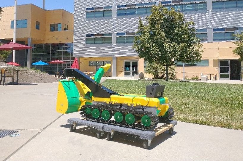
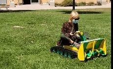
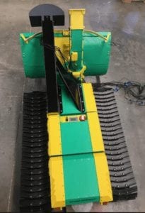
The hardware developed on this project was primarily to demonstrate the proof of concept for an unmanned ground vehicle capable of snow removal. The software aspect of this project was a challenge for our skillset as engineers and slightly beyond the scope of our talents as burgeoning engineering talent. Some examples of further growth are to further the initiatives of:
 
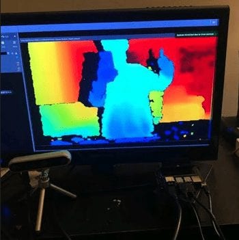
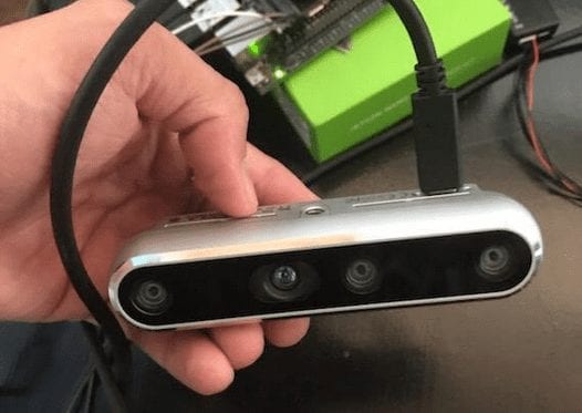
1) Stereovision with OpenCV on the NVIDIA Jetson Nano and Intel Realsense D455 as a companion computer for the Pixhawk microcontroller with to program object detection and vision odometry to navigate the robot. 
2) Robot Operating System (ROS) is a robotic architecture to control the plethora of sensors and electronics onboard the robot. 
3) Machine behavior for human-robot interaction with guests
4) Weather Data API and feedback for autonomous deployment and path state reconnaissance
Cybersecurity protocols to protect the system from malware and theft
 
 
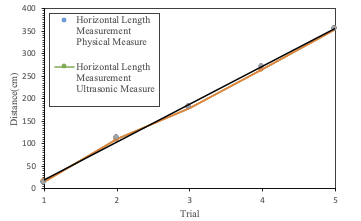
The testing of this system remains speculative given the timeframe of completion for this project. A few examples of improvements to the testing are:
 
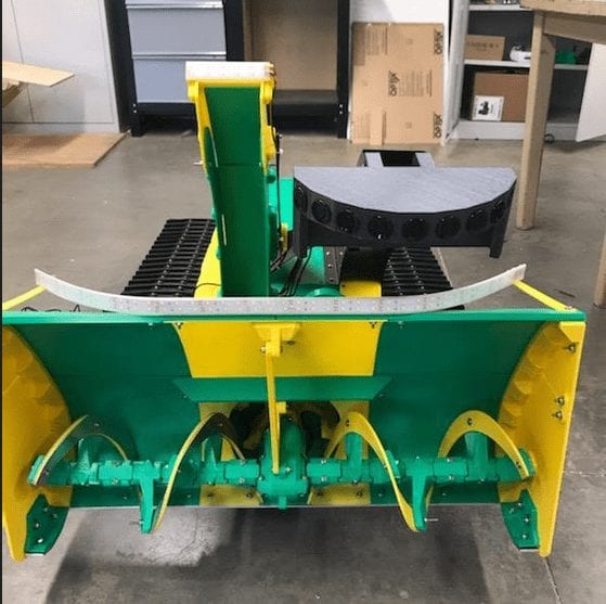
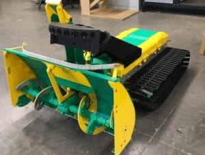
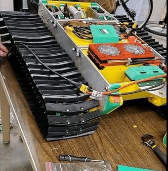
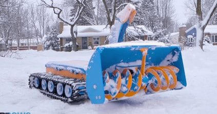
Track build and material for maximum mobility in snow and low friction surfaces
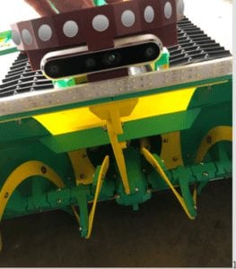
Auger runtime and redesign for mechanical efficiency
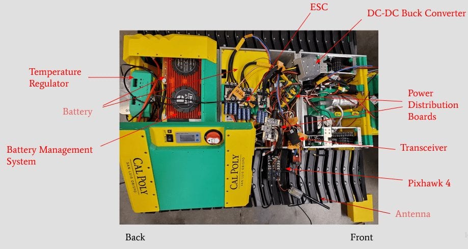
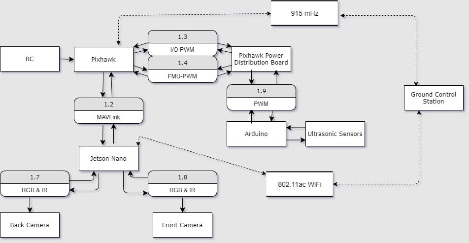
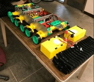
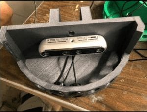
The electronics need to be optimized for space savings. Wires take up a lot of space in the in design and need organization
An autonomous docking station as a home for the robot
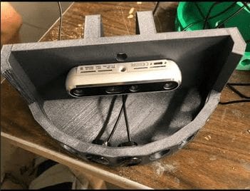
Thermal controls for battery and camera systems
 

Future Application

  • The SnoBot is at the crossroads between robotics and a home appliance. The future of the domestic robotics industry is one of significant promise and increasing marginal utility. This industry is notoriously difficult to enter into because of the unique complexity of the home layouts Brands image of like iRobot, Boston Dynamics, and DJI as singularities in the consumer robotics industry. It is incredibly difficult to penetrate the consumer electronics market for these devices. Similar to this, a SnoBot or similar UGV poses an impressive chance to redefine the way we think about clearing snow from our roadways, domiciles, and walkways. The future vision of a home that services itself and is, in many ways, alive alongside the homeowner.

Our Project Gallery

Share

Share on facebook
Share on twitter
Share on linkedin