Sophie Spencer
CPWP EXPERT
Michael Reyna
Flow sim wizard
Loi Nguyen
mill maestro
Maggie Nevrly
strain gauge novice


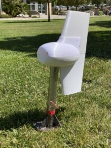
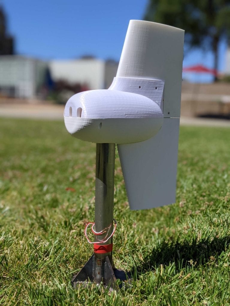
Cal Poly Wind Power Club
This project is sponsored by Cal Poly Wind Power Club as a part of the National Collegiate Wind Competition for the National Renewable Energy Laboratory and the Department of Energy.