Sustainable Energy Storage

The built prototype demonstrates the ability to store energy sustainably in the form of rotational energy. The flywheel is used as a mechanical battery, allowing for charging, storing, and discharging of energy.

Our Team

We are a motivated group of students passionate about renewable energy and sustainable storage. Throughout the year, our team grew together and produced some amazing results. Our diverse skillset allowed for successfully building a fully-functioning, complex prototype.

Alyse Coonce

Project Manager/ coordinator

I am a 4th year Mechanical Engineering major and Mathematics minor, and next year I will be continuing my education in with a BMS in Mechanical Engineering. I have been the contact point for project stakeholders and ensured the projects successful completion. 

Jack Linchey

Manufacturing & Design Co-Lead

I am a 4th year Mechanical Engineering student graduating at the end of this quarter. I worked on the manufacturing of our prototype and spearheaded the integration of our braking and bearing subassemblies.

DSC_7597-Edit-2

Jake Grillo

Manufacturing & Design co-leaD

I am a 4th year Mechanical Engineering student with a concentration in Energy Resources. I primarily assisted with the design and manufacturing of this exciting project. This venture will be a great stepping stone into the real world!


Nick Schnorr

Electronics/Control systems Lead

I am a 4th year BS Computer Engineering / MS Computer Science major. On this team, I designed both the software and hardware necessary to integrate with the mechanical system developed primarily by my teammates.

Acknowledgements

We’d like to thank our sponsor, Mr. Harish Bhutani, whose vision and support made this project possible. Special appreciation to those who assisted us throughout the manufacturing and testing processes – IME Lecturer Trian Georgeou, shop technician Eliot Briefer, and lab assistant Colin Harrop.

Also, a huge thank you to our faculty advisors, Dr. Peter Schuster and Dr. Muhammed Noori. Through their  guidance, design suggestions, and encouragement, our project was able to flourish.

Project Video

F51 - Sustainable Energy Storage Poster

Problem Statement

Households in developing areas need offgrid power storage that is both cost efficient and scalable. The current products on the market largely rely on chemical batteries to store excess energy. However, these batteries have a large cost on the environment to both produce and recycle

Objective

Create a residential sustainable energy storage system that is capable of storing overproduced power from solar panels during the day and supplying this power during the night.

Design Process

Four leading alternatives to chemical battery storage were identified – magnetic, kinetic, thermal, and super capacitor. Ultimately, a kinetic flywheel storage system was chosen for the following reasons:

  • Inexpensive
  • Low maintenance
  • Efficient
  • Feasible given our time, experience, and capability

Different flywheel configurations were then ideated and compared, yielding a final design direction of a vertically oriented system.

Subassemblies

Our main system is comprised of six main subassemblies – flywheel, bearing, braking, chassis, motor, and control system.

Figure 1: Rendered CAD model of flywheel system with steel siding.
Figure 2: Skeletal view of CAD model without steel siding.

Flywheel Subassembly

Figure 3: Flywheel subassembly

The flywheel subassembly is comprised of the flywheel, shaft, and retaining ring. The flywheel is a solid aluminum disk that is 14 inches in diameter and 3 inches tall. The steel shaft is custom machined from Misumi.

bearing subassembly

Figure 4: Lower bearing assembly with 25mm roller bearing and thrust needle bearing in custom machined housing.
Figure 5: Upper bearing assembly of 20mm roller bearing.

braking subassembly

Figure 6: Braking subassembly

The braking subassembly consists of a first generation Mazda Miata rear brake assembly, a crossbar to connect to frame, custom aluminum brake spacer, and bolts.

Chassis subassembly

Figure 7: Chassis subassembly

The main support system of our prototype is comprised of steel rectangular tubing with 1 in cross section and 1/8 inch wall. Most pieces are fully welded together, while the top portion is bolted down to allow disassembly.

MOtor subassembly

Figure 8: Motor subassembly

The brushless DC motor (specifically chosen for low rpm and high torque applications) is connected to the shaft with a coupler and is supported on top of the system by a series of motor mounts and rectangular bars.

Control System subassembly

Figure 9: Control system subassembly

The Arduino takes in inputs from the control box and provides the corresponding outputs to the motor driver. The Arduino also controls the relays which switch between charging and discharging power from the flywheel.

Cal Poly Mark

This project is sponsored by Mr. Harish Bhutani

Engineering Analysis

As the system is a large rotating assembly with many associated safety risks, engineering analysis during all design phases was extremely important

Figure 10: FEA of shaft step

A step was designed to vertically support the total weight from the flywheel and brake rotor. To verify the correct thickness, a simple FEA model was run. We determined a maximum deflection of 0.0001 mm in the step, which was insignificant.

Figure 11: Overall energy storage and losses of system

With the given material properties and dimensions, the flywheel theoretically stores 80 J of energy when spinning at an operating speed of 200 rpm. Due to bearing frictional losses and windage losses due to drag, the system encounters an estimated 0.069 N-m of torque loss.

Figure 12: Motor torque

This curve shows the torque of the motor versus output speed. Since the motor has a 5:1 gear ratio, the speed should be divided by 5 and the torque multiplied by 5. This BLDC motor maintains a high torque even at high rpm.

Figure 13: Speed vs. energy curve

This chart shows the theoretical energy stored in the flywheel versus the speed of the flywheel. As the rpm increases, the energy stored does as well.

Manufacturing

The bulk of our manufacturing took place in Mustang 60 and the Hangar machine shops at Cal Poly. We began with our custom manufactured parts; these included the shaft, aluminum disc, bearing housing, and brake spacer.

Figure 14: Shaft on the lathe
Figure 15: Aluminum disc being faced
Figure 16: Bearing housing with countersink
Figure 17: Brake spacer

Next, we prepped for welding the chassis by cutting bar stock and grinding down the edges. These were then passed off to a shop tech to be welded.

Figure 18: Bar stock being prepped for welding
Figure 19: Fully welded chassis

Afterwards, the steel plates were welded on and all mechanical parts were assembled.

Figure 20: Main assembly with steel plates

Finally, the control system was integrated with the main assembly. The prototype was then ready for testing.

Figure 21: Control system

Verification Prototype

Specifications
Weight: 150 lbs
Dimensions: 17″ x 17″ x 13″
Maximum Operating Speed: 250 rpm

Figure 19: Verification Prototype

Custom Components

  • Thrust bearing housing
  • Aluminum flywheel
  • Shaft
  • Chassis
  • Brake spacer
  • Motor mount
  • Test floor mounts

Stock Components

  • Brake assembly
  • Roller and thrust bearings
  • Motor
  • Fasteners
  • Hand brake

Testing

All testing was done on the strong floor of the Structures and Composites Lab to ensure safe operation.

Figure 20: Testing on the strong floor

completed tests and results

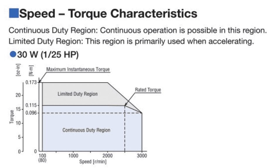
Maximum Power Output:  This test was done to measure the amount of power that the system can supply instantaneously. The system should have the capacity to provide a larger output when necessary, but just for a shorter time period. This will determine what appliances the final design is capable of powering.

Result: We recorded a maximum power of 35 watts. This passed our testing criteria.

Sustained Power Output:  The purpose of this test was to measure the amount of time that the system can provide a typical power output for. This system needs to provide power for an extended amount of time. As the rpm decreases, an acceptable power output should still be possible.

Result: We recorded that the system could provide a normal output for around 22 seconds. This was lower than expected due to the high amount of friction in the bearings.

Noise Measurement:  This test was done to determine the noise output of the entire system when run at high speeds. 

Result: It passed our testing criteria with a value of about 27 dB.

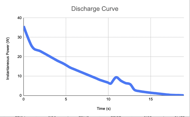
Power Loss:  To determine the total length of time that the system can dissipate charge to the load without any additional power, we simply charged the flywheel and then let it decelerate to a stop.

Result: This test was below the expected value, with a time of 32 seconds.

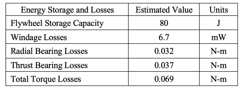
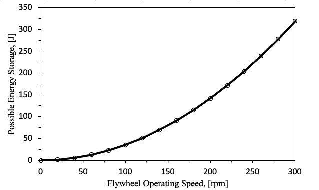
Storing Capacity:  This test was done to find the total amount of energy that the prototype system can hold and output given our maximum rpm.

Result: We measured a total power of 211 J, which was more than we expected.

Charge Time:  To figure out how long it would take to charge the flywheel, we measured the total amount of time it took to accelerate to 250 rpm.

Result: It took 150 seconds to completely charge. This passed our testing criteria of a five minute maximum charge time. We also note that the motor is capable of charging faster if the torque overload alarm is turned off.

Brake Time:  To figure out how long it would take to stop the flywheel, we measured the total amount of time it took to decelerate from 250 rpm to stopped.

Result: With just the motor brake, it took 9.7 seconds to come to a complete stop. While this result is good, it did not pass our initial criteria.

Figure 21: Discharging power output

This chart shows the results of the power capacity test. The area under the curve represents the maximum power that can be stored and taken out of the system. This comes out to around 211 J when the flywheel starts at full charge (250 rpm).

Conclusions & Recommendations

Although this was a proof-of-concept prototype and not a commercial product, we were still able to demonstrate the  functionality and feasibility of a flywheel for kinetic energy storage. Despite limitations on manufacturing processes, we were still able to produce a well-balanced flywheel that successfully operated above 200 rpm without excessive vibration or safety concerns.

Improvements to be made if storage system were to be re-designed:

  • Roller and thrust bearings should be replaced with magnetic or air-ride bearings because they introduce substantial frictional losses into the system, decreasing the usable energy storage. Additionally, system could be housed in a vacuum chamber to further reduce friction.
  •  
  • Since system is decently balanced, the operating speed could be increased without introducing further safety concerns. A new motor would have to be purchased to support a higher rotational speed. 
  •  
  • Incorporate a braking system from a low friction application to work in tandem with the motor’s braking capability.
  •  
  •  
  •  

Have a Question About this Senior Project?

Send an email to pschuste@calpoly.edu to be connected with the project team. Please include the title of the senior project you’re inquiring about in the subject line.

Interested in Sponsoring a Mechanical Engineering Senior Project?

Visit our Sponsorship Page to learn more!

Check Out More Projects!

Visit our ME Senior Projects Page to view the latest Mechanical Engineering senior projects from the class of 2021!

Share

Share on facebook
Share on twitter
Share on linkedin