For future iterations, we offer the following recommendations:
We suggest that the changes outlined in the table below are made to the dimensions of the appropriate parts.
| Part | Previous Dimension | New Dimension |
| CAM wheel outer diameter | 1.4” | 1.3” |
| CAM wheel casing outer diameter | 2.25” | 1.625” |
| CAM wheel casing thickness | 0.15” | 0.1” |
| Distance from bottom of tube housing to lower centermark of slot | 0.51” | 0.41” |
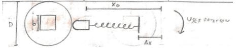
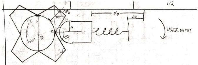
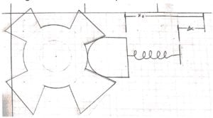
| Distance from bottom of tube housing to upper centermark of slot | 1.71” | Calculate using desired maximum tension according to x=d/(μ*k*D)*Flig+0.3″ |
| Slider base thickness | 0.25” | 0.2” |
| Threaded end cap thickness | 0.25” | 0.2” |
| Spring | See note below |
We suggest that all parts made from polycarbonate, SLA, and silicone rubber are instead made out of 316L stainless steel. This will increase the device reliability and should eliminate the risk of galvanic corrosion from using different metals.
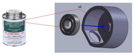
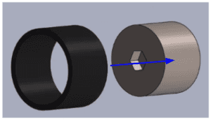
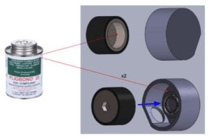
We suggest that the tube casing and the CAM wheel housing are welded together rather than attached using an adhesive. This will make assembly easier and will increase device reliability.
We suggest that the spring to be used in future iterations is made of 316L stainless steel and has the following parameters: an outer diameter of 0.825”, a wire diameter of 0.095”, a free length of 4”, a solid length of 2.75”, a spring coefficient of 24 lbf/in, 28 turns, and closed ends. This design will prevent buckling in conjunction with the inner diameter of the tube, as there is only 0.05” of diametral clearance between the spring and the wall.
We suggest that both the bullet and CAM wheel are cast out of 316L stainless steel and machined to the desired surface finish.
We suggest that the new coefficient of friction between the bullet and CAM wheel is found by casting a large block and a 0.6” diameter disc, placing the disc on top of the block, tilting the block until the disc slips, and analyzing with statics. Once this has been done, the distance from the bottom of the tube casing that corresponds with a specific output tension can be found according to the following formula: x=d/(μ*k*D)*Flig+0.3″, where d is the diameter of the pinion on the gap balancer, D is the CAM wheel diameter, k is the spring constant, and μ is the coefficient of friction.
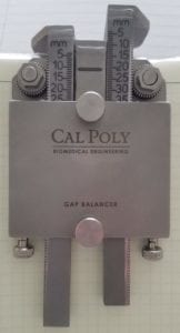
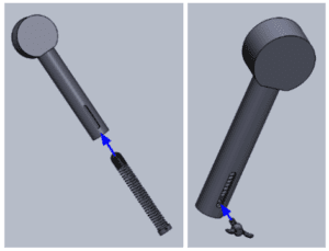
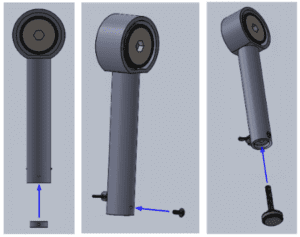
We suggest that the indicator screw be removed and that the slider base be made into a solid disc, with the end farthest from the CAM wheel being used as the reference point for the scale. This is because in practice, the indicator screw hurt ease of use rather than helping.
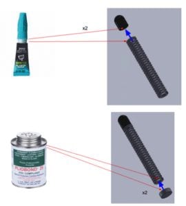
We suggest that the spring, bullet, and slider base are welded together rather than using adhesive to increase reliability and make assembly easier.
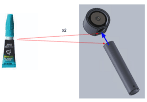
We suggest welding the threaded end cap to the tube casing rather than attaching it using a screw to decrease device bulk and increase reliability.


