Our Team

Gelene Amog
Hello, my name is Gelene Amog and I am a senior and grad student studying biomedical engineering at Cal Poly. I have been involved in QLP for almost 3 years and I am excited to help improve physical therapy for veterans.

Clara Lin
I am a fourth-year biomedical engineering student at Cal Poly from Palo Alto, California. I am passionate about biomedical engineering and working with QL+ because it allows me to apply my engineering skills to improve the lives of others. Last summer, I worked as an R&D Engineering intern at Boston Scientific using optic fibers to treat kidney stones. I am currently pursuing my Masters degree at Cal Poly with a focus on biomechanics. I plan to graduate in Spring 2021 and look forward to working with medical devices in the future.

Nic Rasmussen
I am a 4th-year mechanical engineering major at Cal Poly. I am from El Dorado Hills, California, and grew up playing sports and loving the outdoors. The past two summers I have had the privilege of interning at Spinlectrix, a startup company out of Burlingame, CA that is creating a flywheel energy storage system. I am proficient in SolidWorks and have experience with Fusion 360. Environmental issues excite me and have led me to take renewable energy courses here at Cal Poly such as Wind Energy Engineering and Solar Thermal Power Systems. Working with people is my favorite part of working and certain doors opening have pushed me to take the Sales Engineering class, and greatly interested me in the technical sales field.
Daniel Tepper
I’m Daniel and I’m a fourth year mechanical engineering student at Cal Poly. It has been an incredible journey working on this project for QL+ and using engineering, design and creativity to help veterans shadowbox. I’m proud of the work we have done and are continuing to do for Walter Reed’s physical therapy program. Post-graduation, I’m looking forward to furthering my education and starting my career in a biomedical/biomechanical field where I can use my engineering skills to make a difference in the lives of others.
Acknowledgements
Special thanks to our advisor Dr. Vladimir Prodanov, Professor Kevin Williams and Vanessa Salas.
Our video
Our digital poster
Problem Statement
The goal of this project is to design an assistive device to allow veterans and service members with a variety of balance abilities to shadowbox safely.

This project is sponsored by Quality of Life Plus. Our challenger is Harvey Naranjo at the Walter Reed National Military Medical Center.

Our challenger is Harvey Naranjo at the Walter Reed National Military Medical Center.
Background
- Shadowboxing is an effective form of physical therapy to improve balance and strength, but this exercise can be challenging for individuals with limited balance abilities.
- Currently, no devices on the market are designed to provide stabilization while shadowboxing. Equipment such as stools, lifts, and walkers are utilized.
- These current stabilization methods are ineffective because they limit the user’s range of motion, do not appropriately support the user’s body weight, or are time consuming to set up.
Design Constraints
User Requirements
- Supports partial bodyweight
- Fits users of different sizes
- Folds for easy storage
- Allows for full range of motion
Engineering Requirements
- Supports at least 125 lb.
- 12 in. adjustable height range
- Compact base dimensions <16 square feet
- 360° of rotation and ability to be locked static
Prototyping & Manufacturing
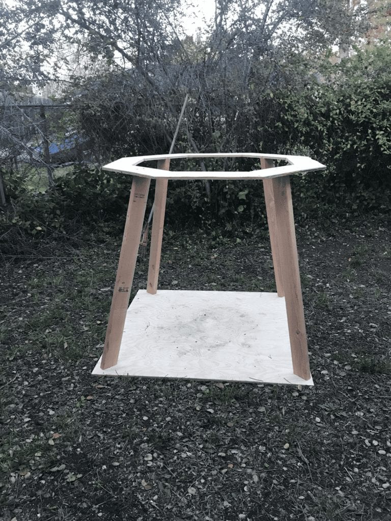
A full-sized conceptual prototype was built out of wood to test resistance band arrangements, lower body support, and user comfort in the device
Manufacturing this device consists of the following key steps:
- Bend legs and cut to the same length
- Cutting aluminum tubes & holes in tubes
- Welding aluminum tubes together
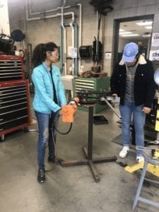
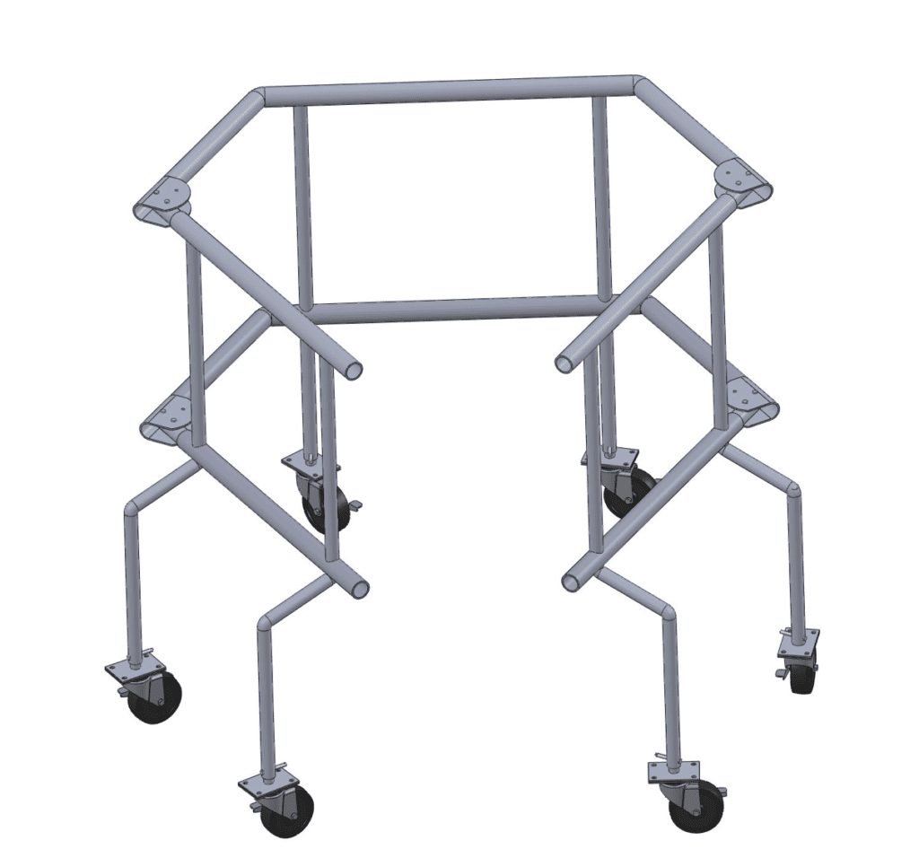
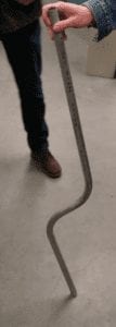
Legs were manufactured out of aluminum tubing using a tube bender machine. Each leg is made from one piece of aluminum tubing and slides through holes in the intersecting tubes. This design simplifies manufacturing and increases strength of the part.
Final Design
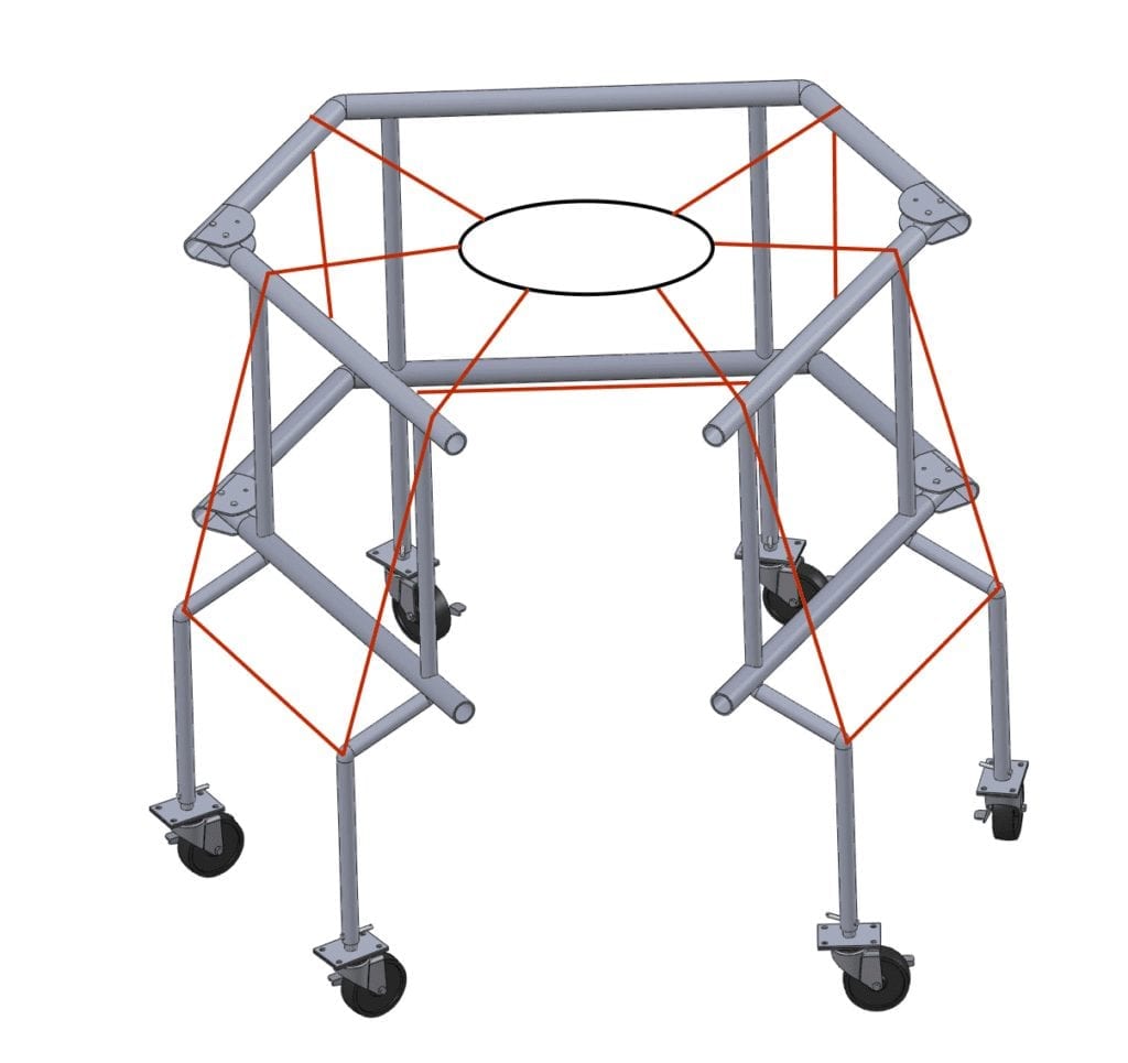
Components
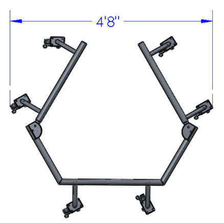
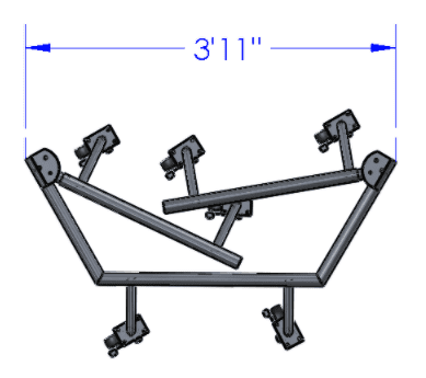
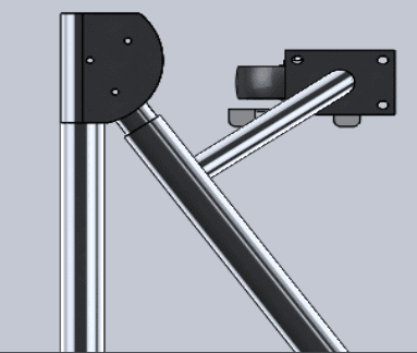
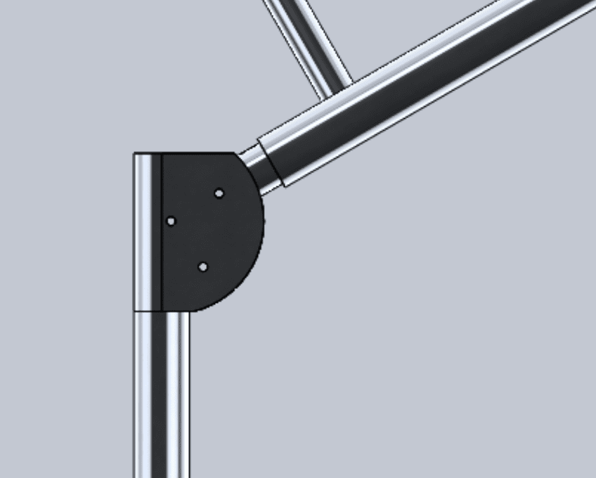

frame
- Material: 6061 Aluminum Round Tubing
- Weight: 24 lb.
- Telescoping leg with pin-lock allows for height adjustability (3’6″-4’6″)
- Hinge folding mechanism for storage
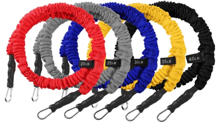
Resistance bANDs
- Sleeved resistance bands prevent user injury
- 5 interchangeable strengths depending on user needs
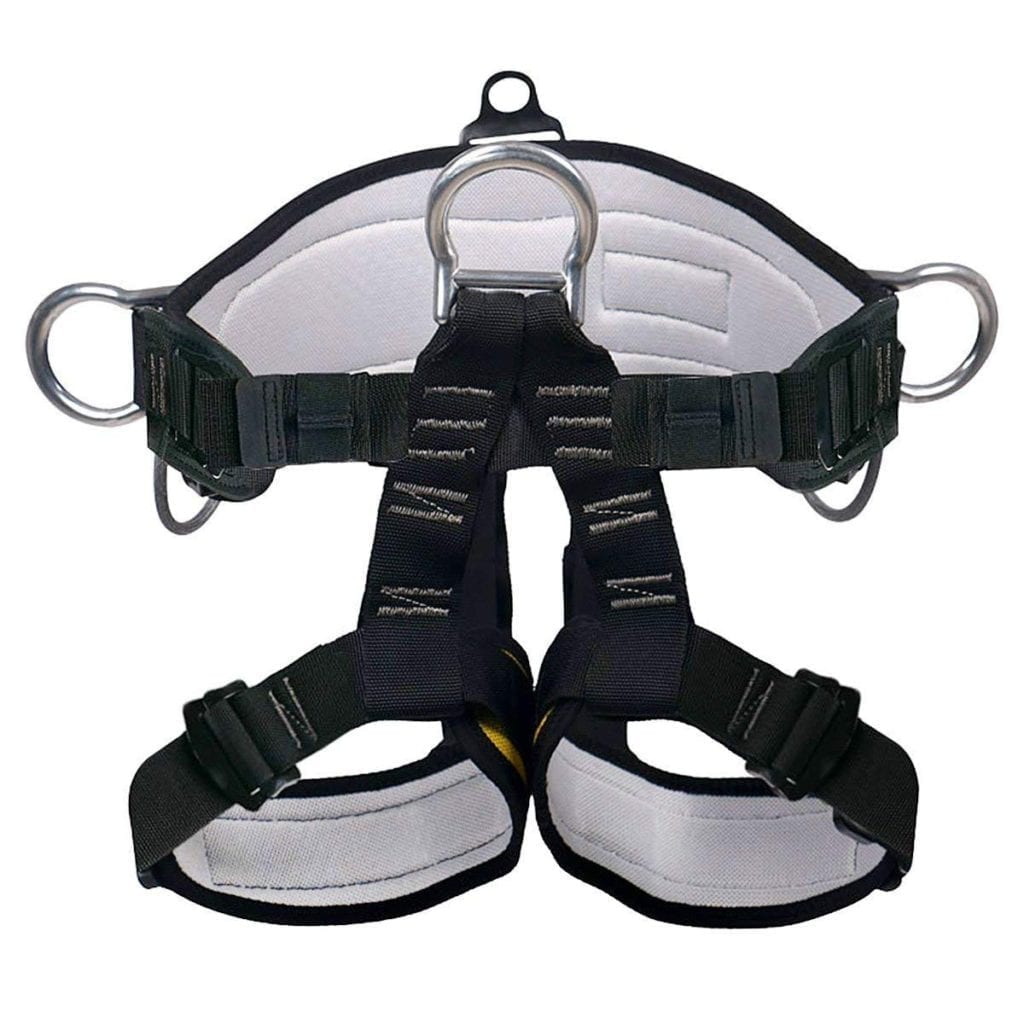
Harness
- Adjustable waist harness allows for full range of upper body movement
- Bands hook onto loops with a carabiner
- Nylon & polyester material for ease of cleaning
wheels
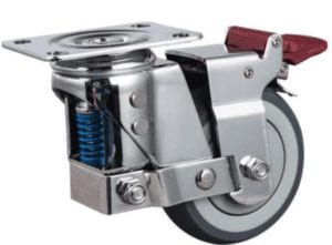
- Spring loaded caster wheel with brake
- Swivels 360° and moves with user while shadowboxing or locks static
- Max. load capacity per wheel: 221 lbs.
- Top plate screws onto plate welded to bottom of leg
Design Verification Testing Plan
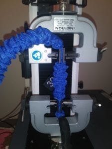
Resistance band testing should be performed to ensure that the band’s elastic properties are still consistent after multiple physical therapy sessions. A 4″ segment of the band will be stretched/relaxed in an Instron tensile test at a constant rate for one hour. The band material properties will be evaluated before and after this test.
Maximum load testing should be performed to ensure that the device frame can support a 250 lb. user. 250 lb. of weights will be placed in the harness attached to the frame and the frame integrity will be evaluated.
Testing & Analysis
Finite Element Model
Case 1 – 250 lb. bodyweight load applied to opening of frame top hoop to simulate user catching their fall
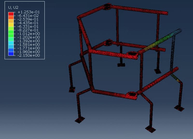
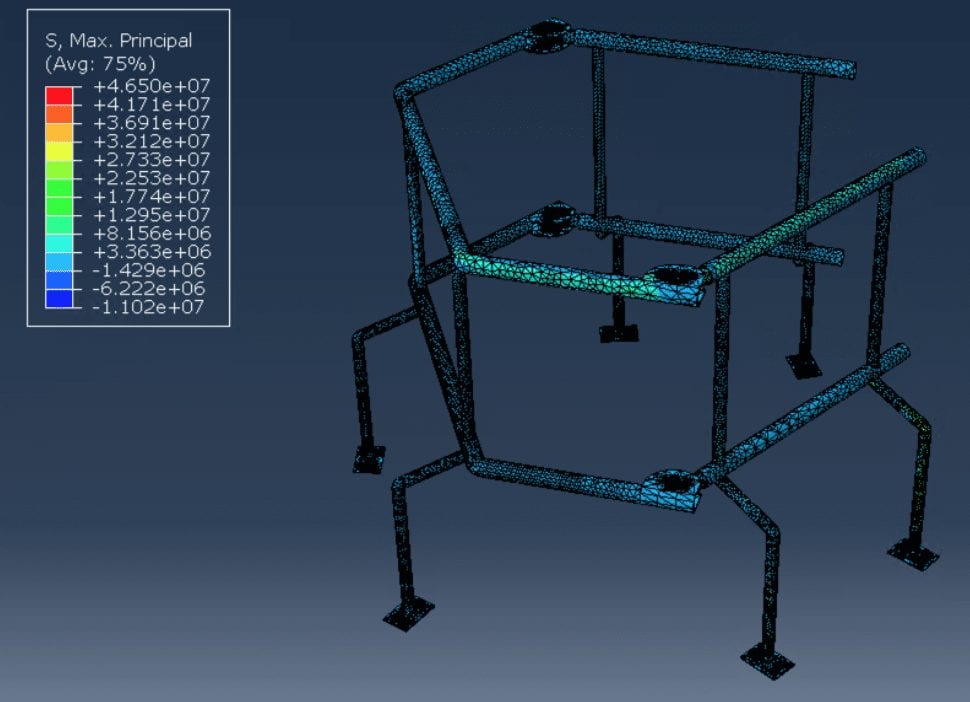
Max. Compressive Stress: 1.60 ksi.
Max. Vertical Deflection: 0.084 in.
Case 2 – 250 lb. distributed among 6 points on the frame (75% loaded downward and 25% horizontally towards the center) to simulate resistance bands
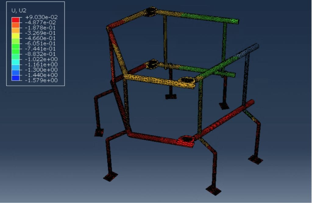
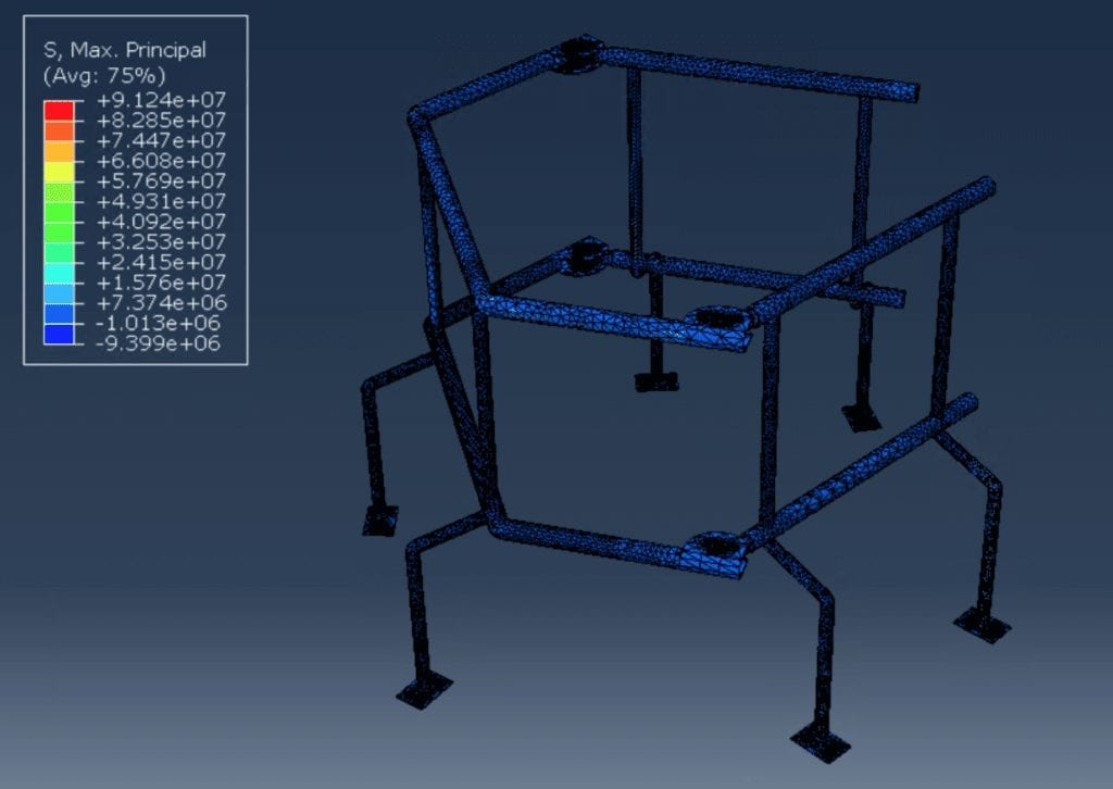
Max. Compressive Stress: 1.36 ksi.
Max. Vertical Deflection: 0.062 in.
Finite element analysis was performed to verify that the frame material and geometry could safely support a 250 lb. user. Simulations with different loading patterns and locked/unlocked wheels were performed.
The results concluded that the frame design and aluminum material met the specification for vertical deflection (<0.1 in.) and peak stress observed was below the yield strength of aluminum (45 ksi).
Resistance bAND tESTING
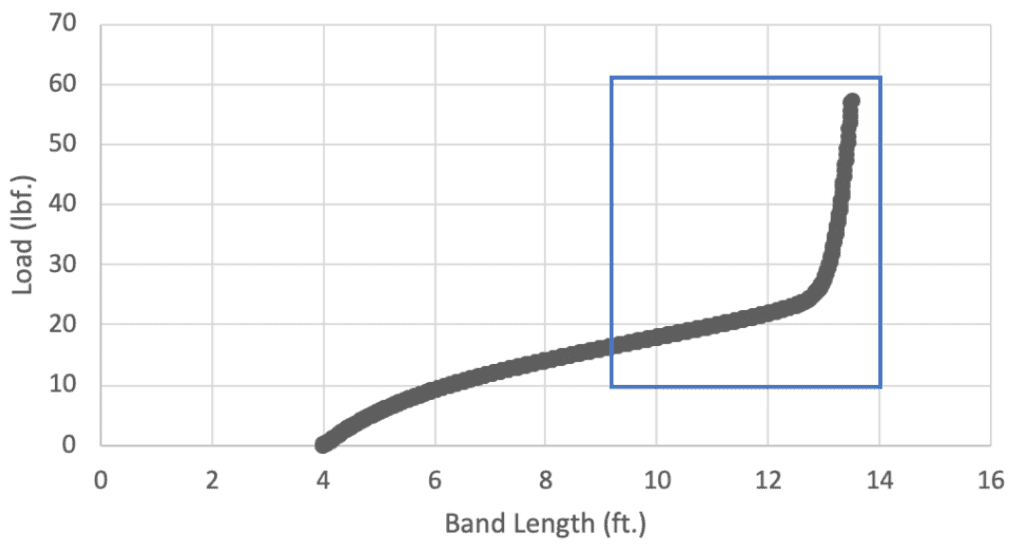
Manual pull testing of the full band using a spring scale and Instron tensile testing of a band segment were performed to determine the loading pattern with respect to band extension.
This length-load relationship was used to determine the ideal band arrangement to support a user’s bodyweight. With our band arrangement, the pre-loaded length of each band hooked onto the frame is 8.3 ft. At this length, the band is at 35% of its maximum load capacity. If five of the maximum strength bands are attached to the device, the initial band load capacity is 147 lb., and this support load will continue to increase as the user stretches the band while shadowboxing.
Future Steps
Due to the Covid-19 outbreak, we were unable to perform any manufacturing ourselves. Our team will hand off the manufacturing drawings, materials, and testing plan for future completion of this project. Next steps include completing manufacturing and testing, then shipping the final device to Harvey Naranjo in Washington, D.C.

