Low Cost Trailer Estimation

The purpose of our project is to aid Professor Charles Birdsong in his automated trucking research by designing a sensor system that can output data on the trailer's motion. This project was inspired by Daimler Trucks of Daimler AG and will hope to aid in the development of safer autonomous truck journeys.

Our Team

We are the Trailer Park Boys and we worked with Professor Charles Birdsong to help in his research on autonomous trucking. Our team designed a system to track a trailer behind an autonomous truck to increase control of the overall computer system. 

Blake Carbonneau

Blake Carbonneau

mechatronics lead

Blake is a Mechanical Engineering major from Redwood City, CA, in the Bay Area. His engineering interest include solving real world problems using mechatronic and/or sustainable energy design. After completion of his undergraduate classes, he will pursue a M.S. degree in Mechanical Engineering with the 4+1 Blended Program here at Cal Poly. In his free time, Blake enjoys working out and playing sports. 

Pouria Fariborzi

Pouria Fariborzi

project manager

Pouria is a Mechanical Engineering major from San Diego. In his spare time, Pouria enjoys playing soccer, hiking, and playing the piano. As a Mechanical Engineer, Pouria hopes to work for companies that aim to do good for society. He will be furthering his education by starting Cal Poly’s 4+1 graduate Mechanical Engineering program in Winter 2021. His main fields of interest are mechanical design and thermodynamics.

Max Lafavour

Max Lafavour

Manufacturing Lead

Max is a Mechanical Engineering major with a minor in Environmental Studies from Seattle, WA. In his free time he enjoys working on cars, DJing, or doing pretty much any outdoor activity. His hands on experience with working on cars in high school sparked his interest in engineering. After graduation in spring, he hopes to enter the renewable energy field or some other field focusing on sustainability.

Acknowledgements

We would like to thank everyone who helped us on this project including our Senior Project advisor, Professor Rossman and our sponsor, Dr. Birdsong. We would also like to thank the the engineers at Daimler, who helped gauge our scope of the project to better fit their needs. 

Digital Poster

Problem Statement

Design a low-cost system to track the real-time angular position and angular velocity of a trailer that is being towed behind a tractor. This system will be mounted and tested on Dr. Birdsong’s existing 1:14 scale model that he is using for his autonomous trucking research. The system should also be able to measure the length of the trailer and must only be mounted on the tractor in order to allow for use with different types of trailers.

Objectives

Initial Design Ideas

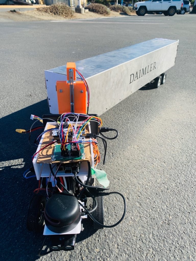
It became clear to us early on in the initial design process that we would have two functions that we needed to focus on: the hitch angle measurement and the trailer length measurement.

Both of these functions would require a method for measuring a value without being able to physically touch the thing that they were measuring. Because of this, we settled on sensors to measure distances and using those distances to calculate the desired values.

We used this decision table to determine which sensors we would use and decided on using Time-of-Flight (ToF) sensors, a smaller, cheaper version of 1D LiDAR. 

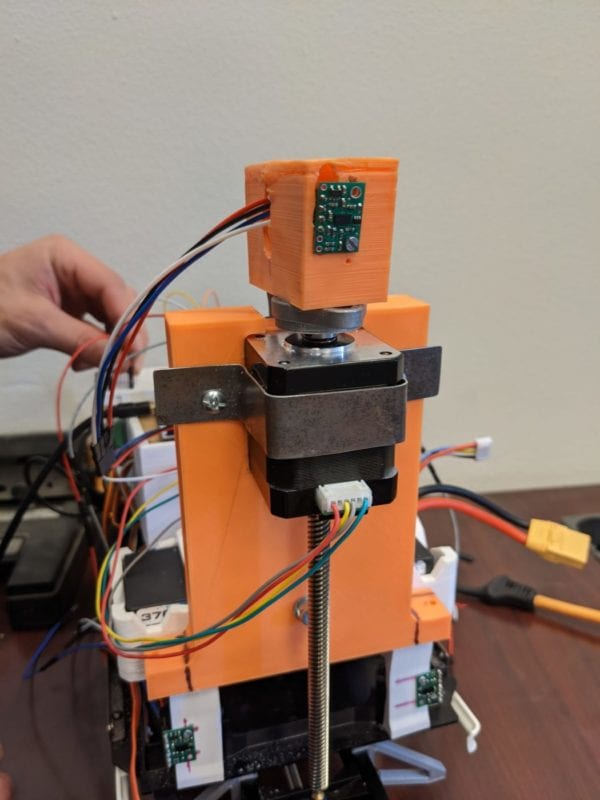
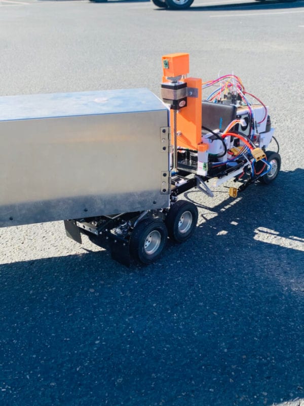
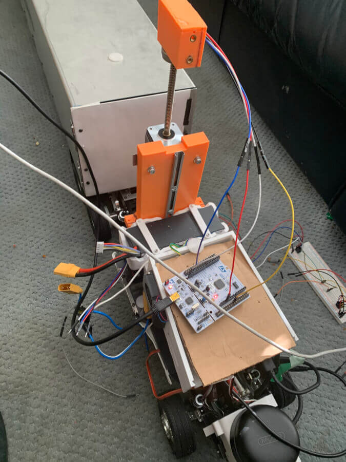
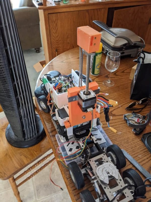
To measure trailer length, a potential solution was to take measurements with a distance sensor to avoid placing any components on the trailer. To accomplish this, we had to design a component to raise the sensor beyond the tractor profile then lower it before the journey takes place.

Cal Poly College of Engineering

This project is sponsored by Dr. Charles Birdsong of the Cal Poly Mechanical Engineering Department

In Conjunction with:

Hitch Angle and Angular Velocity Measurement

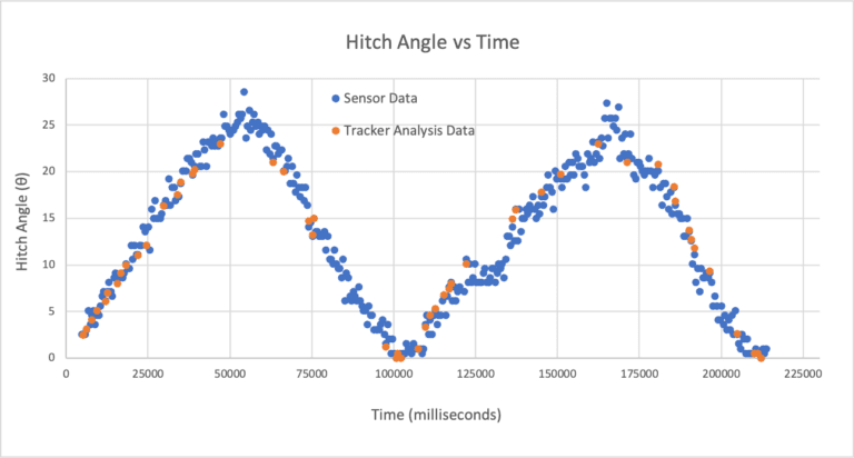
The angular position system had the primary task of outputting the hitch angle (angular position) and the angular velocity of the trailer. 

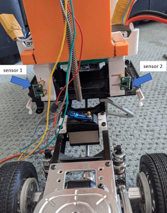
The result was a very simple physical system consisting of two distance sensors, one mounted toward the left of the tractor, and one mounted toward the right of the tractor, which would measure the distances from each sensor to the face of the trailer. As the trailer angle changes, the difference of the distances would be used with trigonometry used to calculate the angle. A derivative function is then used in the microcontroller to get the angular velocity.

There were two existing pillars that were part of the tractor’s superstructure which we were able to use as mounts for the sensors.

Trailer Length Measurement

The length measuring system is more complex. We needed a way to measure the length of the trailer without touching it. 

Design Solution: 

  • ToF sensor placed on the shown mounting block, at a known angle fixed atop a lead screw on a through type stepper motor
    • stepper motor allows for sensor to be raised and lowered to be within tractor profile limit 

Sensor Mount that sits atop lead screw

The distance from sensor is used in a trigonometric relation with the known mount angle to calculate the length. 

 The stepper motor had to be mounted near the top of the tractor profile to allow for the largest lead screw, but still within our .5 inch profile limit.

Manufacturing: A mount is needed to hold the stepper motor and  the sensor on top of the stepper motor. The stepper motor was to be attached to a custom mount using preexisting holes in the tractor’s frame. 

Final Design

The sensors and stepper motor were controlled using an STM32L476 microcontroller. The original intention was to implement our functions into the existing truck’s autonomous framework, but due to COVID-19, we had to use a separate controller for our project.

Angle Measuring Function

Solution Components: 

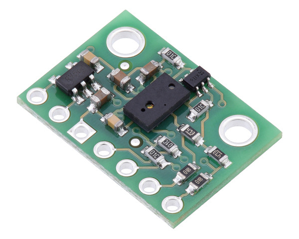
  • two ST VL6180X ToF sensors 

Features: 

  • 1 mm resolution 
  • equipped with an ambient light sensor to adjust for error from intense UV light
  • easy to mount on the tractor with existing mounting holes 

Assembly: To mount the sensors, brass inserts were installed in the vertical superstructures of the truck frame to allow the sensors to be fixed to the tractor with screws.

Trailer Length Function

Solution Components: 

  • ST VL53L0X ToF sensor to measure the distance to the back edge 

  • DRV8825 stepper motor driver by Pololu

  • custom perf board to mount the motor driver and wire all of the sensors together 

Implementation:

  • closed-loop controller where the stepper motor translates up until a large change in distance is detected 
    • signifies the end of the trailer length; stepper motor would then translate back down to the distance before the large change
  • allows for all trailer lengths to be measured

“>

Manufacturing/Assembly Components

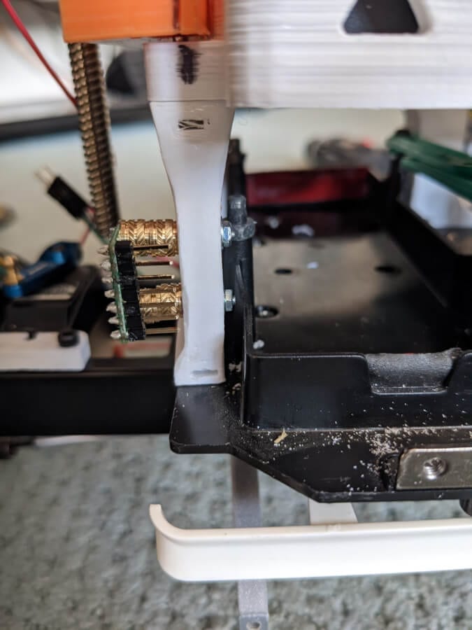
  • 3D printed motor mount 
    • intended to hold the motor in a milled pocket 
    • mount is fitted to the tractor’s existing superstructure
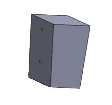
  • 3D printed sensor mount
    • fixes the sensor at 7.5°
    • sits atop a bearing to prevent the mount from rotating with the shaft
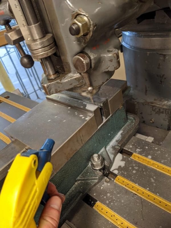
  •  motor bracket
    •  18 gauge sheet steel that was cut into a strip, bent, and drilled to hold the motor 
  • metal sliding rail
    • attaches to the back of both the sensor mount and motor mount in order to keep the sensor pointing straight while translating
    • slot machined up the middle of the inner piece to accommodate the mounting screws

Software Flowchart