Our Team
Hello, we are a group that is passionate about energy and how we can get the most out of the natural world we are a part of.

Tim Holt
Tim is a fourth year Mechanical Engineering major in the general concentration. He has worked for a solar company for several years and that has inspired a deep appreciation for renewable energies. This project caught his eye as it was in that realm but would broaden his perspective about renewable energy.
Joe Blakewell
Joe is studying Mechanical Engineering at Cal Poly with a minor in Exercise and Sport Studies. He has previous work experience in the energy industry thorugh internships. He joined this senior project team in order to gain insight into working with renewable energy.

Kevin Vartan
Kevin is a Mechanical Engineering major with a general concentration. He has interned several summers at Northrop Grumman Corporation, so the aerodynamic loading of this project related to some of the work he has done in the aerospace industry. He has appreciated working on this project and learning more about the renewable energy sector.
Acknowledgements
We would like to thank our project sponsor, TTP for the weekly meetings and especially Dr. Sharon Donohoe and Vineesh Agrawal for their advice and the lessons about life in industry. We would also like to thank our project advisor, Professor Eileen Rossman, for her patience and understanding with the special circumstances of this senior project and this doozy of a year.
Our Project's Videos
Our Project's Digital Poster
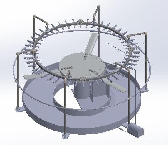
Water Delivery System
Specifications:
32.5 mm/hr rain intensity
2 mm diameter drops
20 cm gauge length
Nozzles >20cm above sample
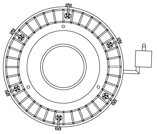
Rainfall area within radiuses of 0.90m-1.10m
Structure
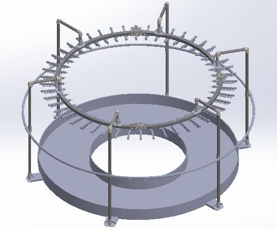
- Legs made of 1″ SCH 40 galvanized steel pipe and threaded fittings
- Ring made of 4 x 90° 3ft radius curved zinc-coated steel strut with bolted connections for easy assembly
Fluid Path
- Reservoir
- Peristaltic Pump
- Flexible tubing
- 1 to 12 flow dividers
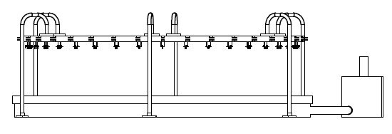
- Dropper configuration
- Nozzles connected by Luer lock
Testing
Goals
- Determine efficacy of design by operating one dropper configuration at design flow rate
- Determine nozzle size needed to produce spec. drop diameter of 2mm
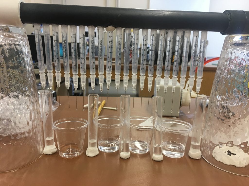
- We tested several nozzle sizes (18 Ga to 34 Ga) by counting drops collected, measuring the mass of water collected, and calculating drop diameter assuming spherical drops.
- We found that at our design flow rate we need nozzles with IDs of 0.09mm or 32Ga.
Fluid Analyses
Pump Selection
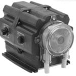
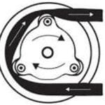
We chose a peristaltic pump to supply our design flow rate because it can provide constant flow rate to meet intensity and drop size specs. Peristaltic pumps use rollers moving in a circular motion to squeeze fluid through flexible tubing. The angular velocity of the rollers is directly related to the flow rate produced by the pump. This allows us to set peristaltic pumps to exact flow rates.
Flow Rate and Pressure Analyses
We created an EES model for our dropper configuration design to show that 20 nozzle outlets from one pipe in a linear configuration will produce virtually equivalent flowrates. The dropper configuration design is shown below.

We created a Matlab model of a pathline in our fluid delivery system to determine the pressure that the pump needs to overcome.
Water Collection and Filtration
Our low-cost filtration system consists of 1 in line filter located in the line coming out of our reservoir, directly before the peristaltic pump. This filters will help keep dust and debris from entering the reservoir to prevent eventual clogging of the nozzles. All of the falling water drops are funneled into the reservoir which the pump draws fluid from.

Turbine Technology Partners
This project is sponsored by TTP.
What is our task?
LE Erosion Issue
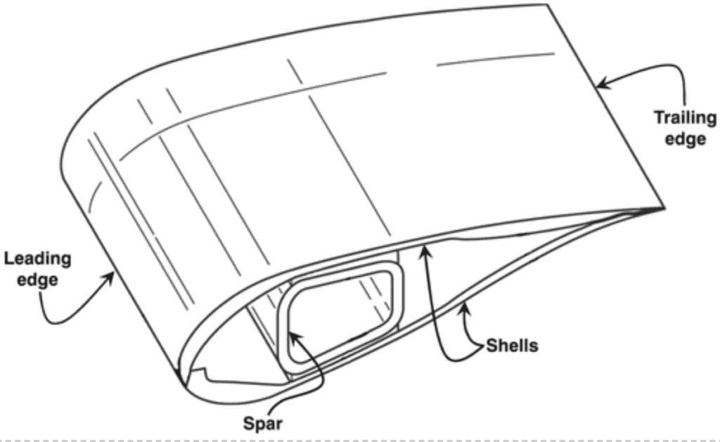
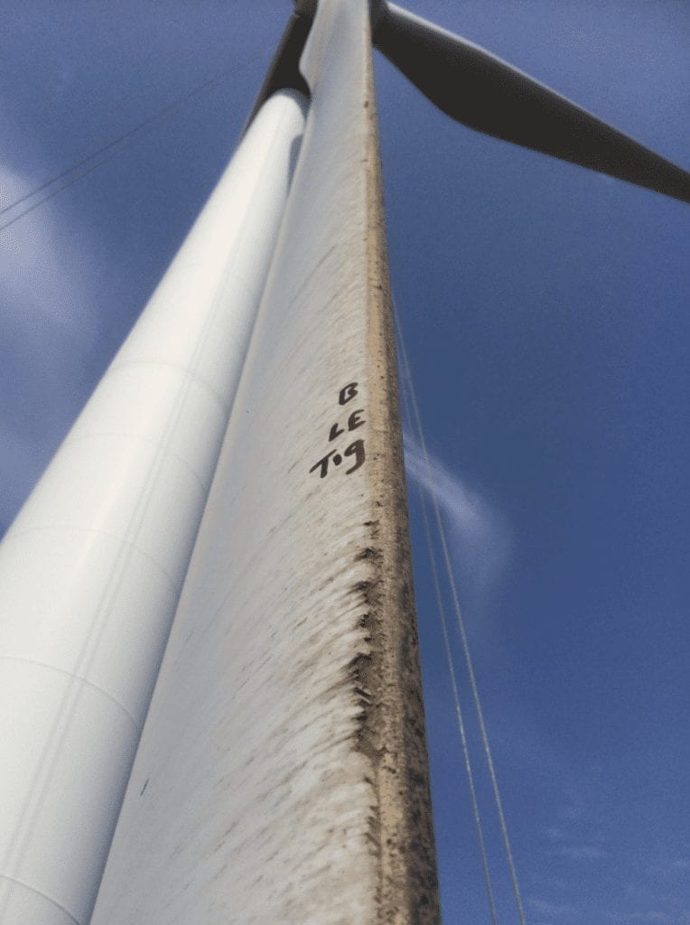
The wind turbine industry is currently plagued with a problem. That problem is Leading Edge Erosion. Wind turbines rotate around 12-15 RPM, which does not seem like it is very fast. A typical 5 MW turbine’s blades are 62 m long, meaning that the tips of these blades can be moving in excess of 250 MPH. When rain hits the blade at such high speeds, the Leading Edge (LE) of the blade delaminates.
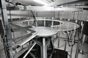
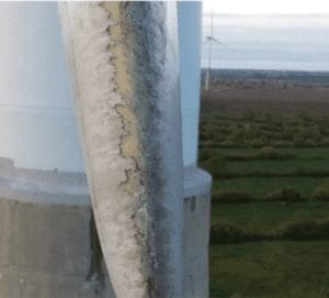
We were tasked with coming up with a machine that tests solutions to the LE erosion problem. After a few hours of research we discovered that there are several machines and an industry best practices that would be our guides. The industry best practices recommends a water drop 2 mm in diameter falls at least 20 cm onto a blade moving at 100 m/s. Given this, we understood there to be two systems, the Water Delivery System that would deliver the rain, and the Rotating Blade System that would spin the blades up to the required speed.
Initial Stages
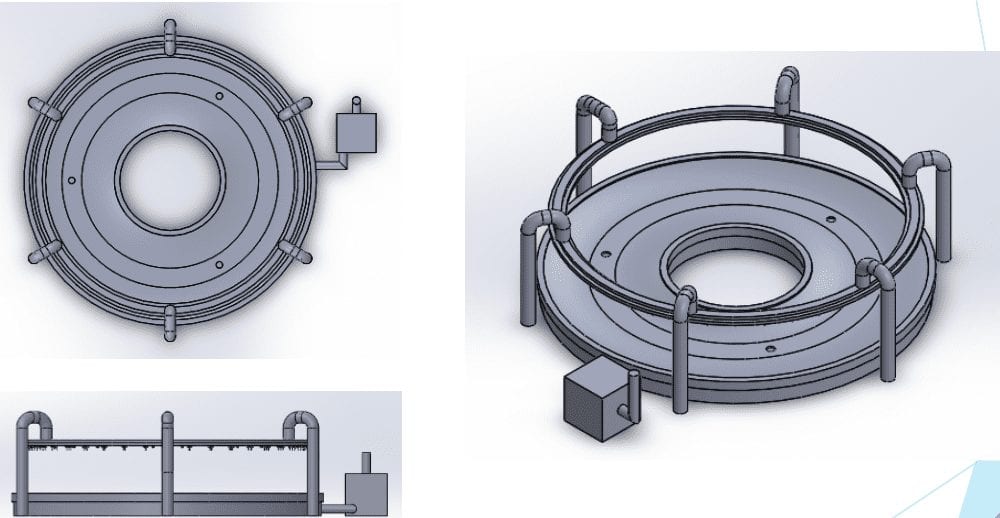
Due to the inherent danger with spinning a blade (recommended to be at least 1 m long) up to 100 m/s, we were tasked solely with designing the Water Delivery System.
Due to complications with manufacturing due to COVID-19, our sponsor preferred that we did not build our prototype for the Water Delivery System but instead continue with design work and design the Rotating Blade System.
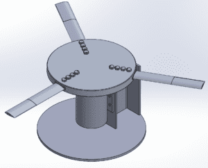
Rotating Blade System
Specifications:
Center of sample moving at 100m/s
DU96-W-180 airfoil shape
Gauge zone 20cm in length
Custom Components
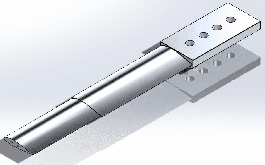
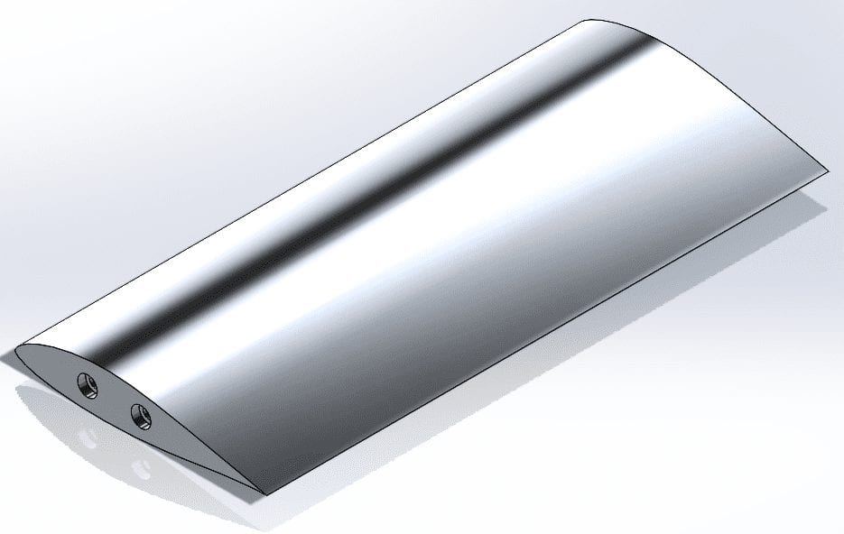
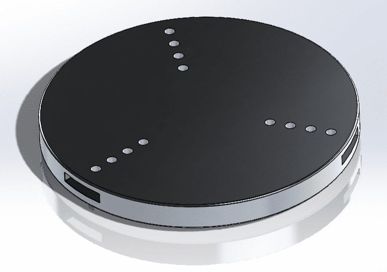
Stock Components
- Bolted connections:
- M6x0.75mm Thread, 30mm long
- M30x3.5mm Thread, 110mm long
- 1/2″-20 Thread size, 2-1/4″ long
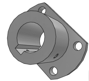
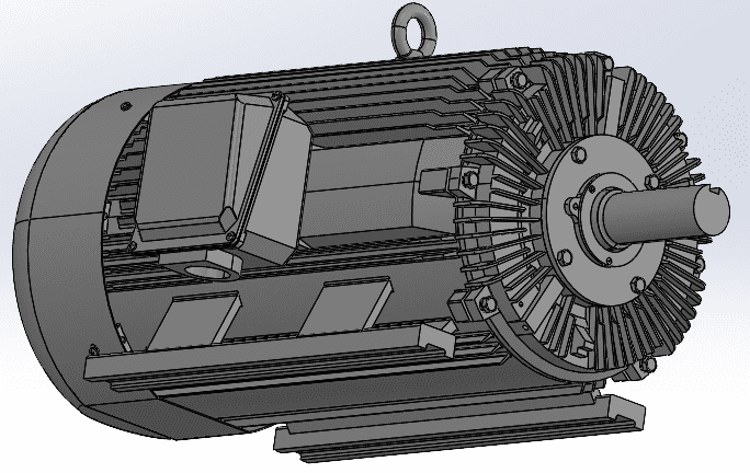
Finite Element Analysis
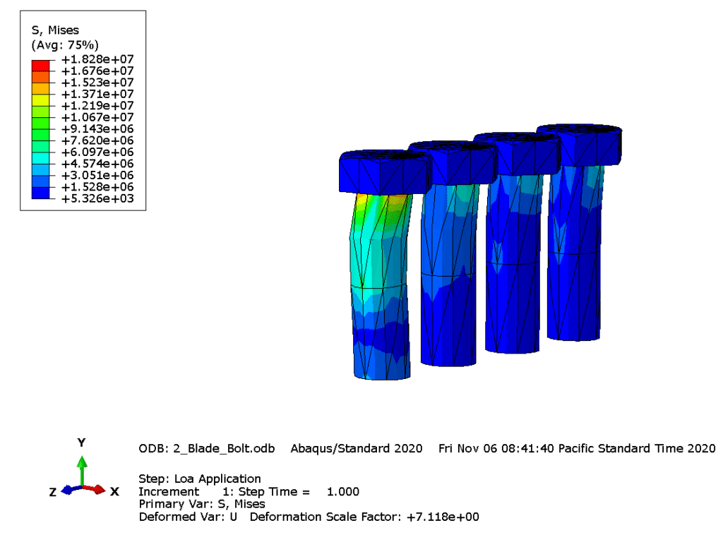
The max Von Mises stress of 18.28 MPa means that the worst-case yielding factor of safety for the bolts is 22.98.
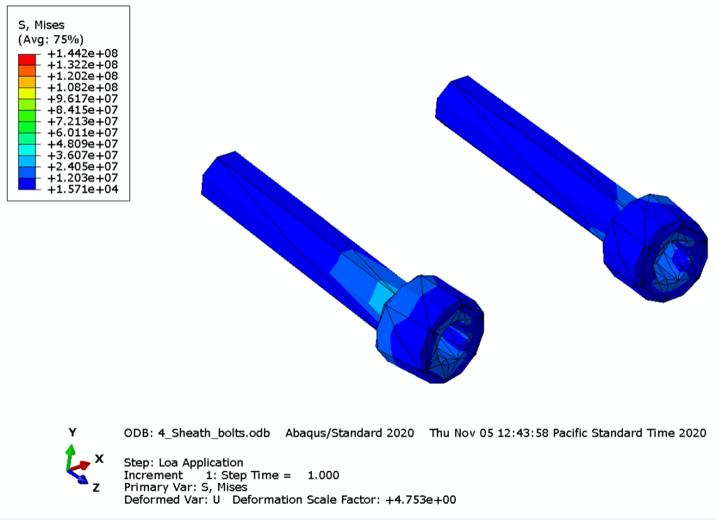
The max Von Mises stress of 144.2 MPa means that the worst-case yielding factor of safety for the bolts is 2.92.
Specifications Check
This section summarizes the specifications that we met for the Water Delivery System and how we verified that we met them.
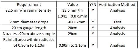
Specifications Check
This section summarizes the specifications that we met for the Rotating Blade System and how we verified that we met them.


