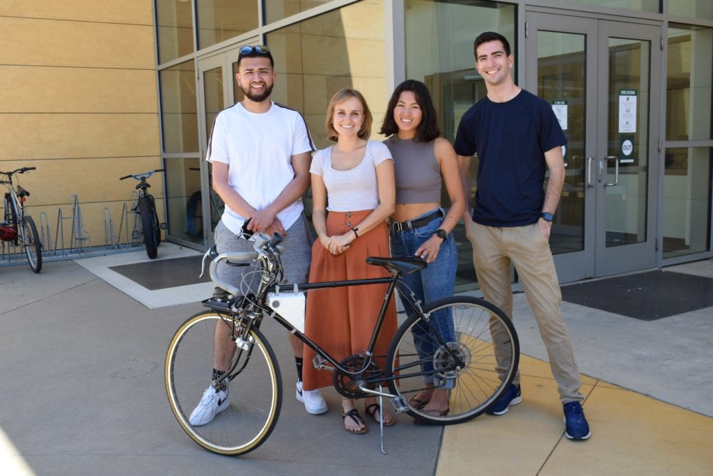
Our Team

Zoe Lam
Mechanical Engineer
Zoe is a fourth year mechanical engineering major and will be working at Auris Health in Redwood City, CA as a R&D Test Engineer after graduation. She is looking forward to using her engineering abilities to help others. In her free time you will likely see her biking, running, surfing, eating, slacklining, or doing anything outside really.

Balthazar Olivier
Manufacturing Engineer
Balthazar is a fourth year manufacturing engineering student interested in automation and data. This summer, he accepted an internship as a field technical service engineer with ifm efector, a sensor and automation manufacturer. He worked on a market potential study and an automation interface When he’s not busy working, he enjoys hiking, mountain biking, or spending time with friends.

Astrid Jouret
Industrial Engineer
Astrid is a fifth year industrial engineering student passionate about sustainability. Last summer she became a continuous improvement and data intern at Covanta, an energy waste company in Philadelphia, PA. Astrid will be working for EDF Renewables in San Diego,CA after graduation. She is entrepreneurially minded and loves spending her free time outside.

Javier Flores
Electrical Engineer
Javier is a fifth year electrical engineering student who is passionate about electrical controls, embedded systems, and electronics. Javier has worked at Diablo Canyon as an Electrical Design and I&C Intern where he learned how to play a role in impactful community solutions. Javier is someone who loves to learn and further expands his electrical engineering skills. In his free time, Javier likes to lift weights, jog, and hike.
Acknowledgements
We would like to thank our senior project advisor, Dr. Vladimir Prodanov and our project sponsor, Brian
Higgins from the VA Medical Center. This project would not have been possible without their feedback and support.
We also want to thank Duncan Applegarth, Kedwin Chen, and the rest of CPES club who gave us
essential guidance with coding for our sensor.
We would like to acknowledge our funding by TECHE and QL+.
Our Project's Videos
The following videos explain the mechanical and electrical components of our bike as well as the additional protective components that were added to protect the electronics from environmental factors.
Our Project's Digital Poster
Problem Statement
Brian is a veteran with retinitis pigmentosa (RP), who enjoys biking both as a commuting method and as sport. Like many others with his condition, he has extreme tunnel vision and night blindness, which means he is not able to perceive potential hazards ahead of him such as other bikers, potholes, and debris.
Objective
Create a system that expands Brian’s sensory inputs, via audible and tactile stimuli such that he can bike with a better sense of what is coming on the surface of the road ahead.
Background
Retinitis Pigmentosa
Regular Vision

Vision with Retinitis Pigmentosa
Retinitis pigmentosa is a genetic disorder causing progressive reduction in sight resulting in pinhole vision and night blindness, around 1/3500 people inherit RP. Brian currently bikes to work around 7 a.m. and back from work around 4 or 5 p.m.. His commute takes him about 15 to 20 minutes but is dangerous due to the fact that he currently only has one sensor on his bike that senses objects directly infront of him. Another concern is that during the shorter winter days, Brian cannot rely on his limited vision because low light conditions decrease his ability to differentiate objects. Our team want to provide a solution that could scan a greater angle on the ground in front of him and alert him of where objects are located (left, right, or center).
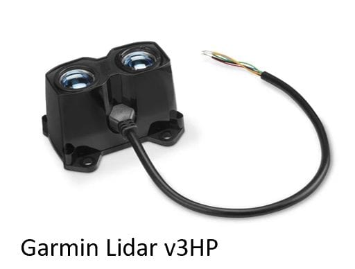
Brian currently has a Garmin Lidar v3HP on his bicycle which alerts him of nearby objects. However this does not help him to detect where the objects are coming from.
Engineering Specifications
Specifications
Total Weight -5 lbs
Does not interfere with regular bike use (bottle cage and bike rack)
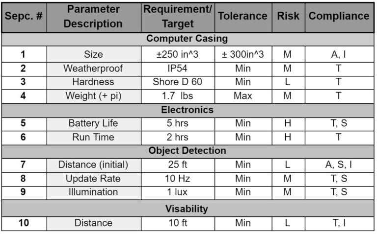
Component-Specific Specifications Below:
Our Solution
RPLidar A1 -360 degree scanner
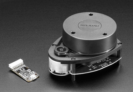
The Slamtec RPLidar A1 provides omnidirectional laser range scanning to generate an outline map of its environment. The sensor has a 360° sweep that was coded to take read specific angles according to user need. The team coded the sensor so that angles:
- 355° to 358° indicate the left.
- angles 358° to 0° and 0° to 2° indicates the center.
- 2° to 5° indicate right.
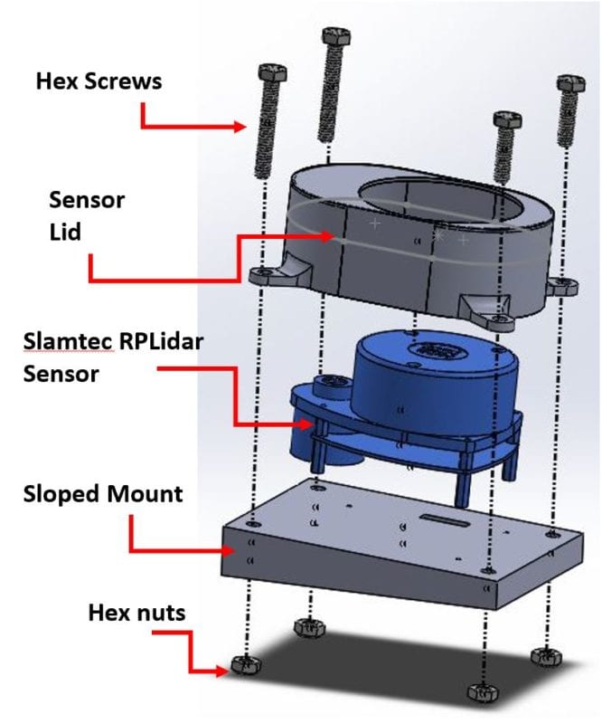
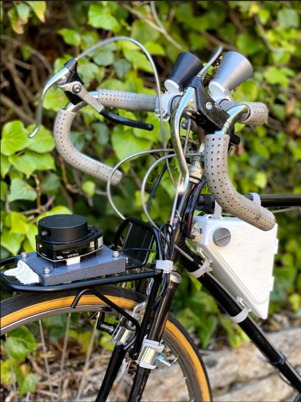
The RP Lidar sensor is mounted on a 4.08° slope that allows it to scan th surface of the road 35 feet ahead. This distance was determined to be the optimal distance that would cause response system to alert the biker and allow the biker to react accordingly with approximately 2 seconds of response time depending on the biker’s speed. The sloped mount is attached onto the front cargo rack of the bike. The Sensor lid on top allows the scanner to rotate while reducing the risk of damaging the electrical components with debris and water.

This project is sponsored by TECHE and Cal Poly QL+
Final Design
Final Design
Our design combines the use of mechanical, and electrical components to meet the customer’s needs. Based on our customer requirements, the design needs to address three categories:
- Detection
- Indication
- System Control
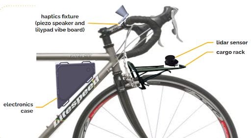
The cargo rack and sensor serve as components for object detection, the haptic feedback fixtures indicate to the user of oncoming objects, and the electronics within the casing power and control the system. For this project the term “haptic” refers to both audible and tactile feedback.
Manufacturing
The cargo rack and all electronics were purchased. The haptics fixture, electronics case, and sensor fixture are all 3D printed using Polylactic Acid (PLA). The electronics were all hand-soldered.
Custom Components
- Electronic Housing
- Housing Door and Latch
- Wire Cap
- Haptics System
- Sensor Mount
- Sensor Waterproof Case
Stock Components
- RPLidar -A1 360 degree
- Scanner
- Raspberry Pi
- 5V USB C Rechageable
- Battery
- 2 Piezoelectric Speakers
- 2 Vibrating Lilypads
- Perforated Printed
- Circuit Board
- Cargo Rack
Haptics System
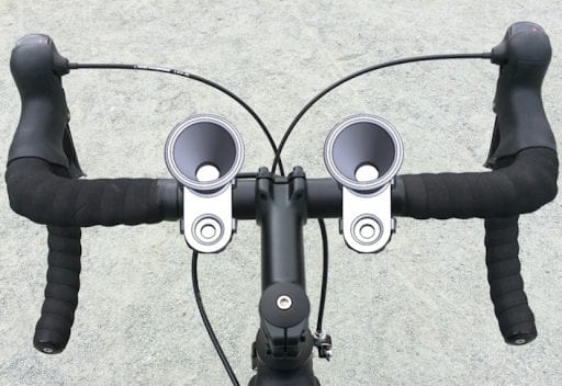
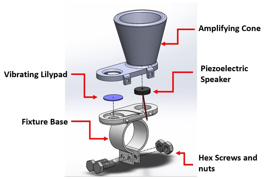
The team created a haptic system that utilizes piezoelectric speakers for auditory feedback and vibrating lilypads for tactile feedback. When an object is detected in the center (angle 358°-2° in front of the user), both left and right haptics fixtures (with left and right lilypads and piezoelectric speakers) will go off at the same time. If an object is only detected on the left only the left speaker and lilypad will be audible and vibrate and vice versa.
The haptics are conveniently placed on the handlebars where the user can easily place his thumbs on the lilypads to feel them vibrate. The amplifying cone helps direct the sound towards the user.
Electronics Casing
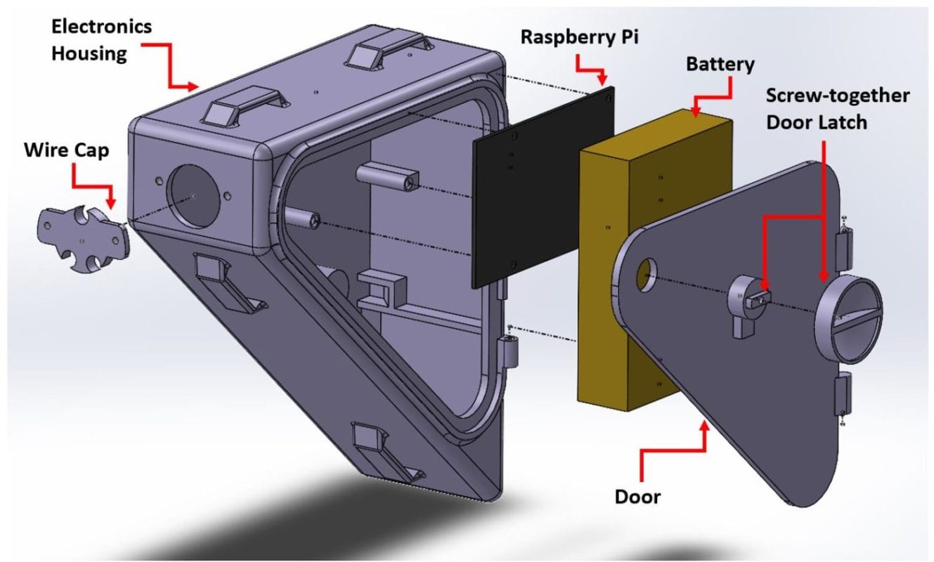
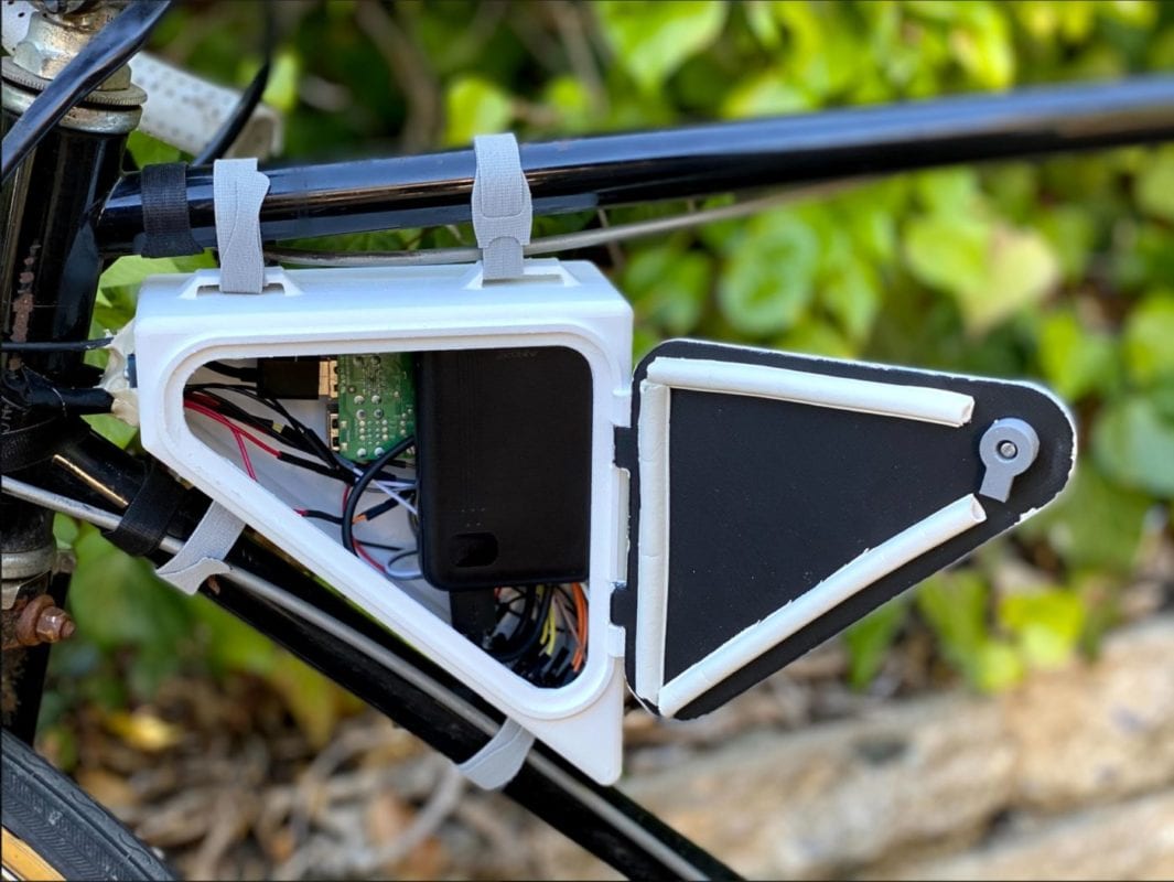
Because our system will be exposed to environmental elements like heat, rain, and road debris, the team created an electronics housing unit that could easily be placed between the top pole and bottom pole of the bike. The hooks on the top of the case allow for the case to easily be fastened on to the frame of the bike with velcro.
The wire cap allows for wiring to easily pass through the case while also limiting the ability for water to pass through. The case is specially designed to hold the raspberry pi, perforated circuit board, and battery. Because the door is made of thin plastic, it is coated in white flex-seal spray to prevent it from deforming in the warm sun. The door latch easily twists open and is screwed together to prevent detaching. There is also a latch stopper located inside the box to prevent the latch from shaking around and accidentally allowing the door to open.
Electronics

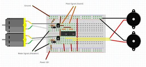
The electronics necessary for the system to inform the user of obstacles or potential hazards are a Raspberry Pi 4B, Slamtec RPLIDAR A1, Piezoelectric Speakers, Lilypad Vibration Motors, and AINOPE portable battery.
Testing
Mechanical Testing
Waterproofing
and
Dustproofing
IP54 rating implies protection from dust and water splashed on the system. All waterproofing and dustproofing tests that subjected the case to environments and circumstances more severe than those expected of an IP54 passed.
Drop Testing and Heat Testing
The mechanical durability testing for the system utilized FMEA methods. Failure modes were identified as seen below:
-The case is no longer waterproof (IP 54 rating)
-The case is no longer dustproof (IP 54 rating)
-The case can no longer keep internal contents contained
-The case does not have four anchor points to the bike
-The rack moves into a position that obstructs the motion and mechanics of the bike
-The rack does not support the weight of the lidar and its fixture
-The sensor fixture does not stay on the rack
None of the aforementioned failures occurred and the system passed.
FMEA Testing
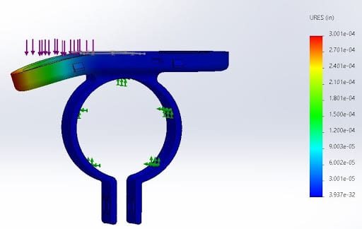
FEA results for displacement in inches. The maximum anticipated deflection is 3×10⁻⁴ inches which is negligible.
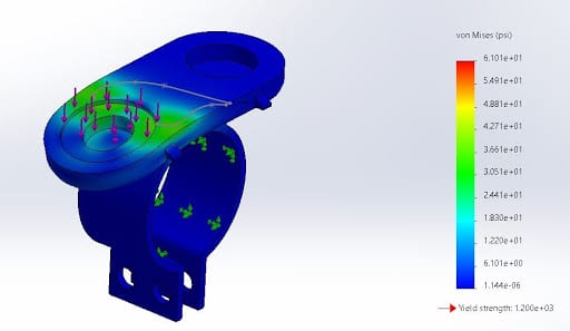
FEA results for von Mises stress in PSI. The yield strength of our material is 1.2×10³ psi while the max stress on the fixture is 6.1 psi.
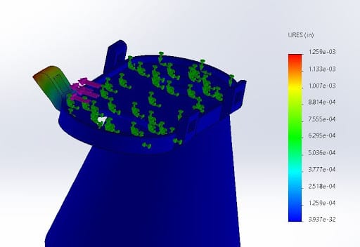
FEA results for displacement in inches. The maximum anticipated deflection is 1.3×10⁻³ inches which is negligible.
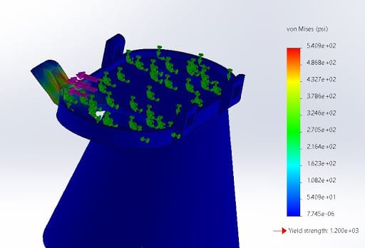
FEA results for von Mises stress in PSI. The yield strength of our material is 1.2×10³ psi while the max stress on the fixture is 5.5×10² psi.
LIDAR sensor and System Testing
Sound Test- Our design was verified by testing the dB reading in the haptic system. The system reads roughly 80 dB wich is enough to be heard in traffic.
System Continuity Test- The system voltage was tested using a multimeter to ensure proper electrical connections
Battery Test- In order for our customer to rely on our sensor, we needed to ensure that the battery life would surpass 5 hours of use. This was tested and exceeded.
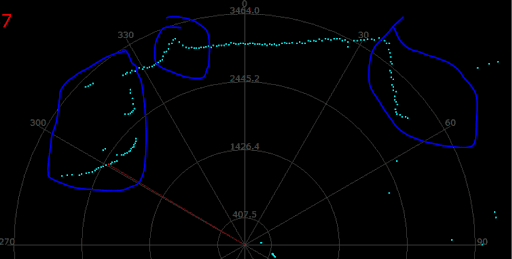
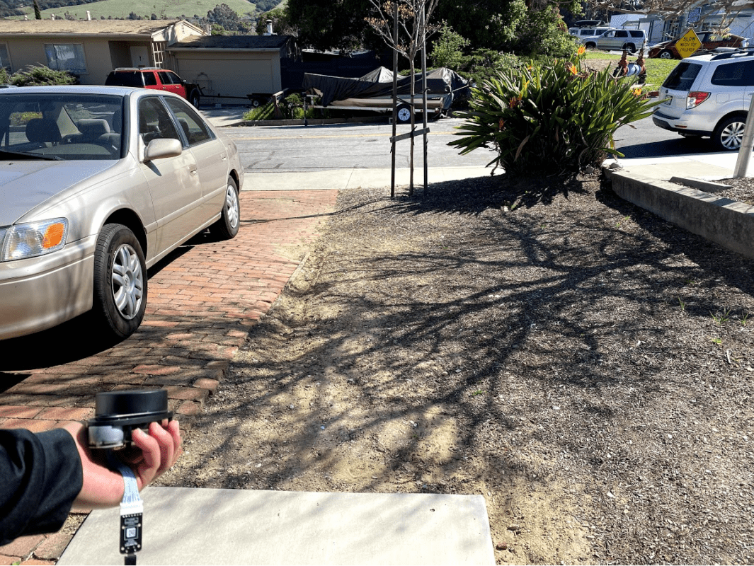
Lidar Scanning Test- In order to pass our safety check, the sensor has to be able to detect objects within 30 feet on the left, right, and center and at different speeds ( from 0 mph up to 20 mph). For safety reasons, the team was unable to test the bike at speeds above 10 mph because the bike had no brakes. The main issue the team had with scanning was that the display would often freeze up because of the amount of loops involved in the code. The system would successfully remain quiet until it had detected something but once it had detected an object, would often stay “stuck” on “Output: On” mode. Often simply riding the bike or shaking the scanner would allow the sensor to get “unstuck”. Ideally the team would have found a way to optimize the code so that there would be less of a chance for the scanner to stay stuck. Unfortunately, due to the limited time on the project and lack of CPE expertise, the team was unable to find an optimized code solution for our customer.
Recommendations
Improvements to be made if feedback system were to be re-designed:
- Optimize detection by increasing audio frequency with increased proximity
- Utilize more heat resistant plastic for electronic casings and mounts
- Add bumper or attention grabbing color to alert pedestrians
Utilize a sensor that could be used for object recognition (3D sensor/camera)
Utilize a sensor that would be better fit for use outdoors (long range infrared or radar )
- Given more CPE expertise and time, we are confident that we can find a method of optimizing the code so that the sensor provides reliable feedback.

