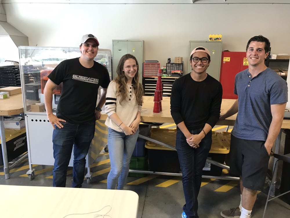
COMPOSITE LATTICE STRUCTURE

Our Team

We are a team of four mechanical engineering students tasked by Maxar Technologies to design tooling and a manufacturing plan for creating their patented composite lattice structure. Being able to manufacture the lattice structure would allow them to test this structure for use on their satellites, making them lightweight and sturdy.

rACHEL GREENE

I am Rachel Greene and I’m from Washington. I’m social and work-oriented at the same time – I like to stay on top of things. I worked at Kenworth on semi-trucks these past two summers but it was great to have a look inside of the aerospace industry and contribute my skills to this project.

iSAIAH DE lEON

My name is Isaiah de Leon and I am a fourth year Mechanical Engineer from Long Beach, California. I have worked with composites in years prior and I have had an amazing time working on this project. I am also very involved in orientation on campus and love working with new students.

Alec fuoti

My name is Alec Fuoti and I am originally from Summit, New Jersey.  I came to Poly so I could obtain a degree which would support my aspirations of going into the aerospace industry.  I am very interested in spacecraft structures and have had some experience in the past in designing them.

patrick o'donnell

My name is Patrick O’Donnell and I am from Temecula, CA and chose this project because I enjoy tooling design and manufacturing.

Acknowledgements

We would like to acknowledge Dr. Eltahry Elghandour for being a supportive advisor and Austin Fisher, our sponsor, for being flexible and helpful throughout this entire process. We would also like to acknowledge Eric Pulse for running and maintaining the Machine Shops, especially Mustang 60.

Our Project Videos

Our Project's Digital Poster

Problem Statement

Maxar Technologies is requesting that students create a method and design tooling for manufacturing their patented graphite fiber reinforced polymer (GFRP) lattice structure so they can produce and test this structure for use on their proprietary satellites. This structure, if manufactured quickly and inexpensively, would significantly reduce the overall mass of their satellite antenna reflector dish structures resulting in significantly reduced launch costs.

Design Objective

  • Tooling used in this process must be ergonomic, modular, scalable and reliable so that Maxar technicians are able to consistently create high quality lattices.
  • Tooling must be able to create a 2 by 4 cube lattice of the structure described in patent #10326209.

Terms and Definitions

Tow – An untwisted bundle of continuous filaments; in this case, the filaments are graphite fibers.

Graphite Fibers – A group of carbon fibers which have a carbon content of about 99% and also have high modulus values.

Prototypes and Ideation

Tow attachment to posts: When deciding how to connect tows to posts, we were limited to options such as wrapping/tying, adhesive, and weaving through holes. The first two options presented too many issues, and drilling holes in the posts to weave the tow through became the clear option.

Weaving process ideation: We realized that the structure was too complex to try and only use one tow, so we moved on to weaving by plane. Each weaving plane has 3 tows which will be woven through it: two tows that are straight, and one that forms the diagonals.

Fixturing the posts: We had to come up with a way to keep the posts in place during the weaving process, and they needed to stay vertically aligned. We came up with a fixture plate to hold them in place and then later realized the need for a clamping mechanism to ensure alignment during weaving.

Small prototype of a single woven cell made out of straws, string, and tape

Prototype baseplate to show the preliminary design of the fixture assembly with a fully woven structure.

Applying pressure to tow during curing: It is beneficial to apply pressure to carbon fiber during curing, often accomplished with vacuum bags, but with our structure we would have had to come up with a very creative solution in order to apply pressure. We thought of ideas like creating silicon inserts of various shapes to press into the cubes before the cure, but in the end decided that if the tows are woven with enough tension, the effect that pressure would have had could be accomplished in a much simpler way.

Tying off the tow: Lastly, we needed a way to tie off the tow from each plane. After a few design iterations we realized that these tie off points needed to accomplish more than what they were originally intended: they also needed to ensure uniform tension across the lattice, and they needed to allow for possible expansion of the tooling relative to the lattice without breaking the tow. We decided that including springs in our design for tying off the tow would solve this issue.

This project is sponsored by Maxar Technologies

Manufacturing Process and Components

Fixturing method for posts on manual mill
Rendered image of full assembly
Carbon fiber particulate evacuation

Fixture Plate: Create CAM to drill and tap the various holes on the fixture plate. Secure stock plate in CNC and run program from operation 1. Check hole positions on CMM to ensure part accuracy.

Clamps: Cut stock to length (20” length, Quantity: 10). Create CAM to mill profiles, drill holes and mill slots needed in each of the clamps. Due to long part length, secure in 2 vices on CNC mill and run program. Press in pins on hydraulic press and check fit on already machined fixture plate.

Tie Down Towers: Water jet stock to length and shape (2.5”, Quantity: 25).  Tap holes on mill. Install tie down bolts.

Carbon Fiber Posts: Cut stock to length (5” length, Quantity: 20). Mill slots using a rotary vise and steady rest on manual mill

Design Verification

Friction Analysis-   In order to gauge the friction loss across the posts, an analysis was performed across an individual post. Since the properties of the tow are proprietary 

Deflection Analysis- A deflection analysis for a singular post was performed to see how much deflection would occur from different force inputs. The calculated value from the analysis is 125 psi of stress in posts per pound of tow tension.

Thermal Analysis- A thermal analysis for the base plate and clamps was performed to gauge the thermal expansion of the tooling at the temperatures of the curing oven (350 degrees F)

Final Design

The base plate (1) locates the posts and anchors the structure. The tie down towers (2) function as a tie off point for the tows, and allow them to hold a controlled tension during curing. The clamps (3) fix the posts in place and keep them vertically aligned during curing. The graphite posts (4) are structural guides for the composite tow.

Tie Down Tower Assembly

The above pictures show in depth the structure of the tie-down-towers. The entire part is manufactured through one operation on the water jet. The main tower (1) is the structure of the part. The back panel (2) holds the springs which are attached to the clips (3) that tie to the tows. The slots (4) give two degrees of freedom to the springs to account for thermal deflection and varying tow angles. The small plate (5) allows for the tie-down-towers to thread into the base plate. 

Full 2x4 Lattice Assembly

Weaving Process

Planar Weaving Process

The weaving process is another important product of the project. We designed a “planar” weaving process where the technician would weave each individual plane of the lattice utilizing the geometry shown in the bottom left picture. The red rectangle in the top right picture shows an example of one of the “planes.”

Conclusion

Potential improvements: Our design can accompany up to a 4×4 lattice structure, but if a larger lattice is needed, it would be beneficial if our tooling included a method of attaching multiple lattices together. Also, since there are springs implemented in our tie down tower design, it would be interesting to modify this design to be able to read a tension force from the tow tie off points by using spring scales at these endpoints.

Lessons learned: After realizing that the tooling would expand more than the carbon fiber structure during curing, we learned that we should consider the effects of thermal expansion earlier in the design process, and how different materials interact when heated. Also, we learned to consider the details of the design as early as possible and redesign as needed.

Image Gallery

Have a Question About this Senior Project?

Send an email to pschuste@calpoly.edu to be connected with the project team. Please include the title of the senior project you’re inquiring about in the subject line.

Interested in Sponsoring a Mechanical Engineering Senior Project?

Visit our Sponsorship Page to learn more!

Check Out More Projects!

Visit our ME Senior Projects Page to view the latest Mechanical Engineering senior projects from the class of 2021!

Share

Share on facebook
Share on twitter
Share on linkedin