Composite LiftWalker for Shurouq

          The picture above shows our final prototype, successfully lifting our team member Daniel Martinez.

The goal of this senior project was to design and build a new version of our project sponsor Charlie Gutierrez’s LiftWalker for Shurouq, our client. Shurouq is a young woman who lives with her family in Egypt. She was born with multiple health conditions which resulted in leg contractures that have since left her unable to walk. Charlie’s device, the New LiftWalker, has helped dozens of people with disabilities similar to Shurouq's. However, Charlie’s standard design is made of stainless steel weighing up to 80 lb, which is both difficult and expensive to send to Egypt. For this reason, Charlie turned to the Mechanical Engineering Department at Cal Poly, challenging us to redesign his LiftWalker out of lightweight composite materials.

Team Shurouq

Daniel Martinez

Designer/ 3D Modeling

I am a third-year mechanical engineering transfer student. In this year-long experience, I learned how to manufacture simple carbon fiber parts and gained a better understanding about the benefits of using composite material for specific applications. It was a great experience working with a group of brilliant students and learning about the intricacies of carbon fiber manufacturing.

Vikram Profile Pic

Vikram Thridandam

Project Management/Composites Lead

I am a fourth-year mechanical engineering student.  My primary interests are in aerospace and biomedical devices, specifically human-centered design.  This project enabled me to apply the knowledge gained from my Cal Poly education to balance the technical and non-technical aspects of an engineering project.  From learning various methods of composite manufacturing in our advisor’s new class, to contacting material vendors and applying to grants, this truly was a holistic project.

Madeline Faase

manufacturing/3d modeling

Over the course of my five years at Cal Poly I have had the privilege of learning the intricacies of engineering problem solving, and last fall I was thrilled to have the opportunity to apply that knowledge to help our client Shurouq.  The carbon fiber layup techniques required for this project were initially new to our team, and I really enjoyed practicing those new skills together in the composites lab over the past year. 

Robert Boyd

Manufacturing Lead

I am a fourth-year mechanical engineering student and will be entering the Blended-Masters program next year. This project has been a great learning experience for me, and I’m so happy that we were able to make a product that will hopefully change Shurouq’s life. Working with different composite materials and manufacturing methods alongside my team has been the high point of my senior year.

Project Videos

Project Digital Poster

Problem Description

Our challenge was to design a custom LiftWalker using composite materials.  We set out to deliver a uniquely lightweight and maneuverable walking device for our intended client Shurouq, a woman in her early 20’s living with her family in Egypt.  She was born with severe muscle contractures in her legs, which left her unable to walk.  Our device will support her as she takes her first steps, and begins the process of learning balance.

Design Concept

3D CAD Model

Components Layout

Base Member Connections

Material Selection

A carbon fiber frame was chosen for the following reasons:

  • The low density of carbon fiber significantly reduces the net weight of the device, and makes international shipping feasible.
  • Carbon fiber has material properties that match or exceed that of the original AISI 304 stainless steel used for the LiftWalker.
  •  Our sponsor likes the aesthetic of carbon fiber, and because it is malleable and can be formed into any shape, it appealed to his creative side.

Other design choices to note:

  • The square carbon fiber tubing was originally intended to be round carbon fiber tubing, but square tubing was selected for ease of manufacturing.
  • An I-beam frame was also considered, but was not selected for its poor performance under torsional loading.
  • AISI 304 stainless steel used for the joints because it’s easier for machining.
  • Carbon fiber diagonal supports were placed between the upright column and base to reduce flexure.

Ideation

During the early stages of the project, the team imagined many different ways to modify the LiftWalker, whether it was adding, removing, or replacing parts, we aimed to improve the function and performance of the device.

  • We considered adding a function for collapsibility to make the device modular and easy to store:
  • We also considered using different wheels and lifting mechanisms:
  • We even considered changing the entire frame:

In the end, our sponsor decided it was best to stick to his configuration and focus on manufacturing an adequate carbon fiber frame.

Our sponsor’s original LiftWalker constructed from AISI 304 Stainless Steel.

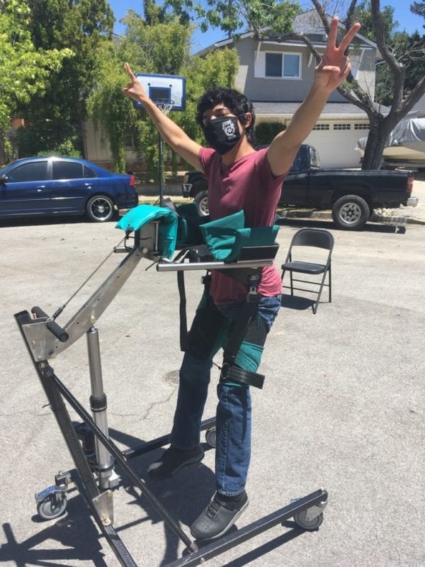
This project is brought to you by the Mechanical Engineering Department at the California State University, San Luis Obispo; Sponsored by Ideomotion LLC, and funded by the Cal Poly Connect and Baker/Koob grant foundations.

Design Evolution

The double-web I-beam is not favored for its bulky size.

Round tubing is too difficult to consistently manufacture without expensive equipment.

Square tubing meets all criteria for the application and is easy to manufacture, with or without equipment.

Design Verification

Compression Test:

Many different tubes of varying wall thicknesses were subjected to compression tests in order to determine the strongest and most viable circular tube. We tested samples made of carbon fiber, Kevlar, and Kevlar-wrapped aluminum, as seen in the figure to the right. 

Tension Test: 

We tested AXIOM carbon fiber prepreg samples with this method to determine the best cure cycle for our application. Since we did not have access to an autoclave, we had to forego the manufacturers recommended cycle so we used the following cure cycle.  This cure cycle is recommended for Toray (formerly Tencate) HX40 AmberTool® prepreg carbon fiber, which is what we used in the new composite manufacturing class at Cal Poly.

Tension test on a 6-ply carbon fiber sample, using a Lloyd Instruments/Ametek LD50 testing machine.

3-Point Bend Test

A 3-point bend test best replicated our actual loading conditions. Shown below are two photos in the composites lab, where we bend tested our doubled webbed I-beam.  The results of this test encouraged us to change our approach.  We found that due to our lack of manufacturing experience, the I-beam failed at 1150 lb when we had hoped it would surpass the 7500 lb  (determined from hand calculations). We would have liked to do more 3-point bend tests, but the campus was closed before we could, due to COVID-19.

Instron 3-Point Test Fixture. 

Deflection Analysis

Finite element analysis (FEA) showed that carbon fiber deflects 0.0053 mm under a 200-lb load whereas stainless deflects 0.0063 mm. This is because carbon fiber has an elastic modulus of 228 GPa, versus 193 GPa for typical stainless steel (AISI 304).

A 200-lb distributed load on the armrest yields a 19 mm downward deflection, but this FEA model omits the linear actuator (which can lift 1000-lb) and diagonal supports.  Therefore, this design is more than sufficient to lift Shurouq, who is just under 100 lb.

Weight Test:

Our  prototype weighed in at 58 lbs which was over our initial design goal, but we were not able to convert the whole frame to carbon fiber due to the lack of lab access caused by pandemic. If the entire frame could be made from carbon fiber, we estimate that the device would weigh as little as 40 lbs.

User-Load Test:

The prototype was able to comfortably lift Daniel and support his entire weight (125 lb). We are confident that this  re-designed carbon fiber LiftWalker model will be completely safe for Shurouq who weighs just under 100 lb.

Final Design

Specifications
Weight – 58 lbs
Lifting Weight – 150 lbs

Recommendations

Improvements to be made in the future:

  • Manufacture carbon fiber tubes with a greater wall thickness in order to reduce the overall flexure.
  • Create the lifting arm mechanism out of carbon fiber to reduce the weight of the device.
  • Design steel joints that are modular in order to add ease of assembly and disassembly for the user.
  • Manufacture molds that incorporate reinforced areas for fasteners and joints to reduce assembly time and increase overall strength of the frame. 
  • Consider integrating triangular plates in the front corners of the frame to prevent twisting in the front beam.
  • The plates can be bonded to the frame with a strong adhesive, but fasteners are recommended for disassembly.

What We Learned

  • Early communication saves a lot of time and effort
  • Carbon fiber manufacturing is tedious but manageable once the layup process is well understood. 
  • Curing multiple composite parts at once saves a lot of time.
  • For the best curing process, vacuum-sealing carbon fiber parts provides high and even pressure around the part resulting in high strength and a great surface finish.
  • Instead of using a vacuum seal, wrapping components in shrink tape before curing also provides high pressure and creates a stronger part, but it is a very difficult task to do by hand.
  • A spiraled uni-directional weave provides the best resistance for torsional loads.
  • The material properties of carbon fiber highly depends on the type of fiber used and the manufacturing process.

Manufacturing a Double-Web Carbon Fiber I-Beam

Part I: Molding the Silicone Core
Machine an aluminum U-channel to hold the silicone core
Sanded and cleaned U-channel
Mix silicone with hardener, pour into U-channel
Let silicone cure for 48 hours, then remove from U-channel
Part II: Composite Layup
Cut strips of carbon fiber
Layer strips for the different plies
Press aluminum tubes against silicone core
Place aluminum plate on top and clamp together, stack weights to apply even pressure, put in oven to cure (10 hours)
Once cured, carefully remove aluminum tubes and silicone core
Unfortunately when trimming down excess fibers, we cut the flange too close, which is where it failed in the 3-point bend test
Previous
Next

Manufacturing a square Carbon Fiber tube

Clean all surfaces
Cut carbon fiber to size
Mix appropriate amount of epoxy
Pour epoxy onto the weave
Press the epoxy into the weave
Wrap carbon fiber around the tube
Let the tube dry before use
Previous
Next

Acknowledgements

Our team would like to thank our instructor, Dr. Eltahry Elghandour, and our sponsor, Charlie Gutierrez, for always showing us their full support and guiding us through the most challenging times of this project. Dr. Eltahry’s expertise helped us develop an understanding of what it takes to make a quality carbon fiber element. Through trial and error and after many iterations of samples and tests, we created a procedure to manufacture good-quality carbon fiber parts that even exceeded the design requirements of our application. Of course, it was also thanks to Charlie Gutierrez who suggested a final adjustment in our manufacturing process that yielded fairly consistent results in terms of size, strength, and stiffness of the desired part and material. Our team would also like to give our thanks to the senior project director, Dr. Peter Schuster, for introducing us to many great people whom we had the pleasure to connect and work with throughout our project. Dr. Schuster essentially paved the way and helped us stay on track, even in these very difficult times during the COVID-19 pandemic. That includes all other instructors involved in the 2019-2020 senior project at Cal Poly SLO: Dr. Sarah Harding and Dr. Brian Self.  Your guidance was essential for our success and your hard work is greatly appreciated.

Have a Question About this Senior Project?

Send an email to pschuste@calpoly.edu to be connected with the project team. Please include the title of the senior project you’re inquiring about in the subject line.

Interested in Sponsoring a Mechanical Engineering Senior Project?

Visit our Sponsorship Page to learn more!

Check Out More Projects!

Visit our ME Senior Projects Page to view the latest Mechanical Engineering senior projects from the class of 2021!

Share

Share on facebook
Share on twitter
Share on linkedin