
Darya Darvish
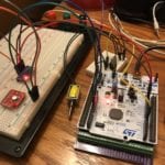
Mechatronics & Testing

Charlie Glenwright
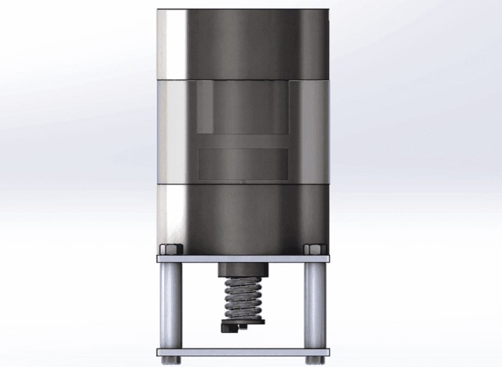
Analysis & Design

Nicholas Olesh
Analysis & Project Management

Tim Wills-DeTone
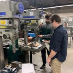
Manufacturing & Testing

This project was sponsored by Dr. Elghandour and Dr. Elbarbary.