Our Team

Arthur Zaayer
Arthur Zaayer is from Clovis, CA. He loves to snowboard in the winter and visit Yosemite in the summer. He will be moving to Santa Barbara following graduation to work full-time

Marius Jatulis
Marius Jatulis is from Thousand Oaks, CA, and his family is from Lithuania, that’s where his name comes from. He loves to surf and ski. He also spends a lot of time working on projects with Cal Poly Space Systems.

Griffin O’Malley
Griffin O’Malley is from San Diego, CA. He loves to surf and do outdoor activities. He also loves designing and prototyping new ideas.

Jose Covarrubias
Jose Covarrubias is a Mexican American from Santa Maria, CA. He love trying new foods and going to new places. He will be moving to Seal Beach following graduation to work full-time.
Acknowledgements
We thank Quality of Life Plus and AmpSurf for sponsoring this project and navigating this unique situation alongside our team, and also ValleyIron for their generous materials donation. We also want to thank our professor, Mrs. Harding, for guiding us throughout the entire process.
Our Project Videos
Surf Sled
Problem Statement
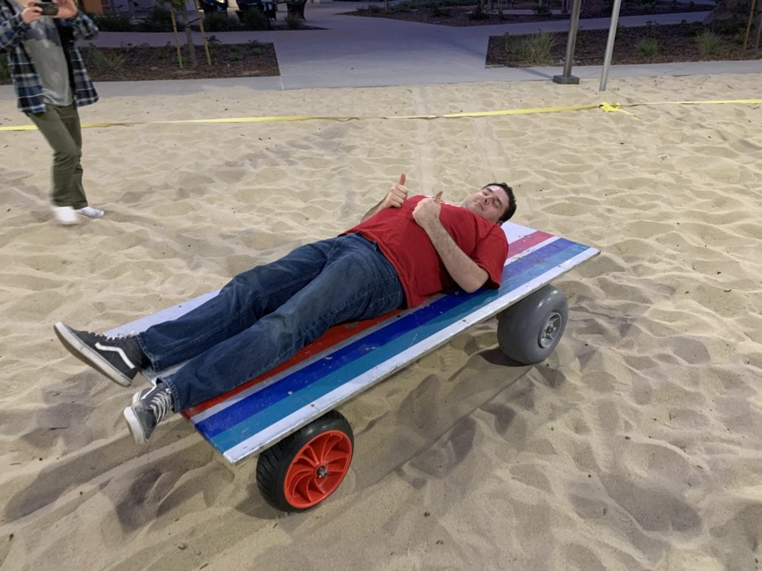
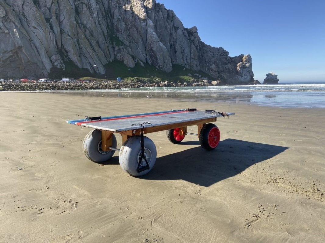
Design and build a mobility product for AmpSurf to help people with lower body disabilities travel from the beach to the ocean while lying on their surfboard. It must be light, reliable, and able to fit into the AmpSurf trailer. The fins of the surfboard cannot interfere upon departure from the sled, and it must be able to be operated by able-bodied volunteers.
Objectives
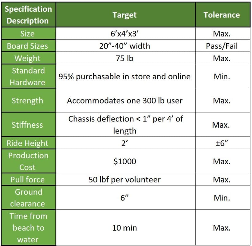
In addition to these design specifications listed above, there were also several design considerations that limited our options:
- AmpSurf uses a large variety of surfboards with different fin configurations, amounts, and lengths. Our design must not interfere with any of these types of surfboards.
- This product will be fully submerged in sea water, and then allowed to rest outside in the sunlight for long periods of time. We must be careful to only use anti-corrosive and waterproof materials to ensure longevity.
- There is a wide range of volunteers that will be using this device, so we must design with simplicity in mind so that minimal/no training is necessary.
Design Concept
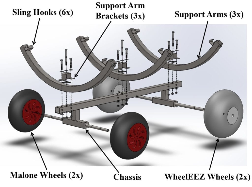
- Less buoyant Malone wheels are required in the front to ensure the vehicle doesn’t pop-up and float in the water immediately following the removal of the Sling underneath the rider.
- 304 Stainless Steel for all metal, and 316 Stainless Steel for the fasteners, was selected due to its anti-corrosive properties and a generous material donation.
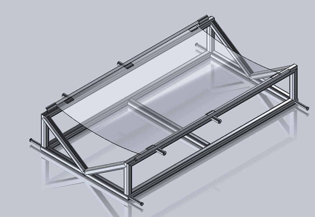
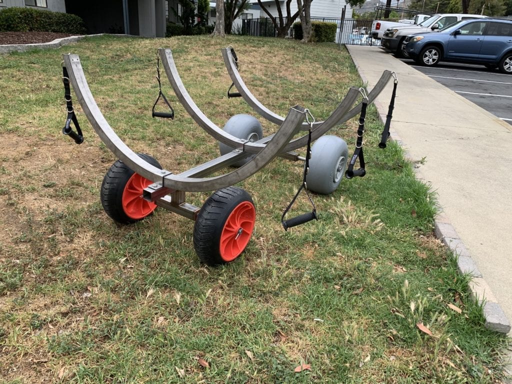
- The sling hooks are cut out of the same 2″x2″ square stock that the Chassis is made of, and then drilled with two fasteners into the support arms.
- The Support Arm design switched from rounded to square members to avoid unnecessary welds. The attachment to the Chassis is now accomplished with the Support Arm Brackets.

This project is sponsored by Quality of Life Plus
Beam Analysis
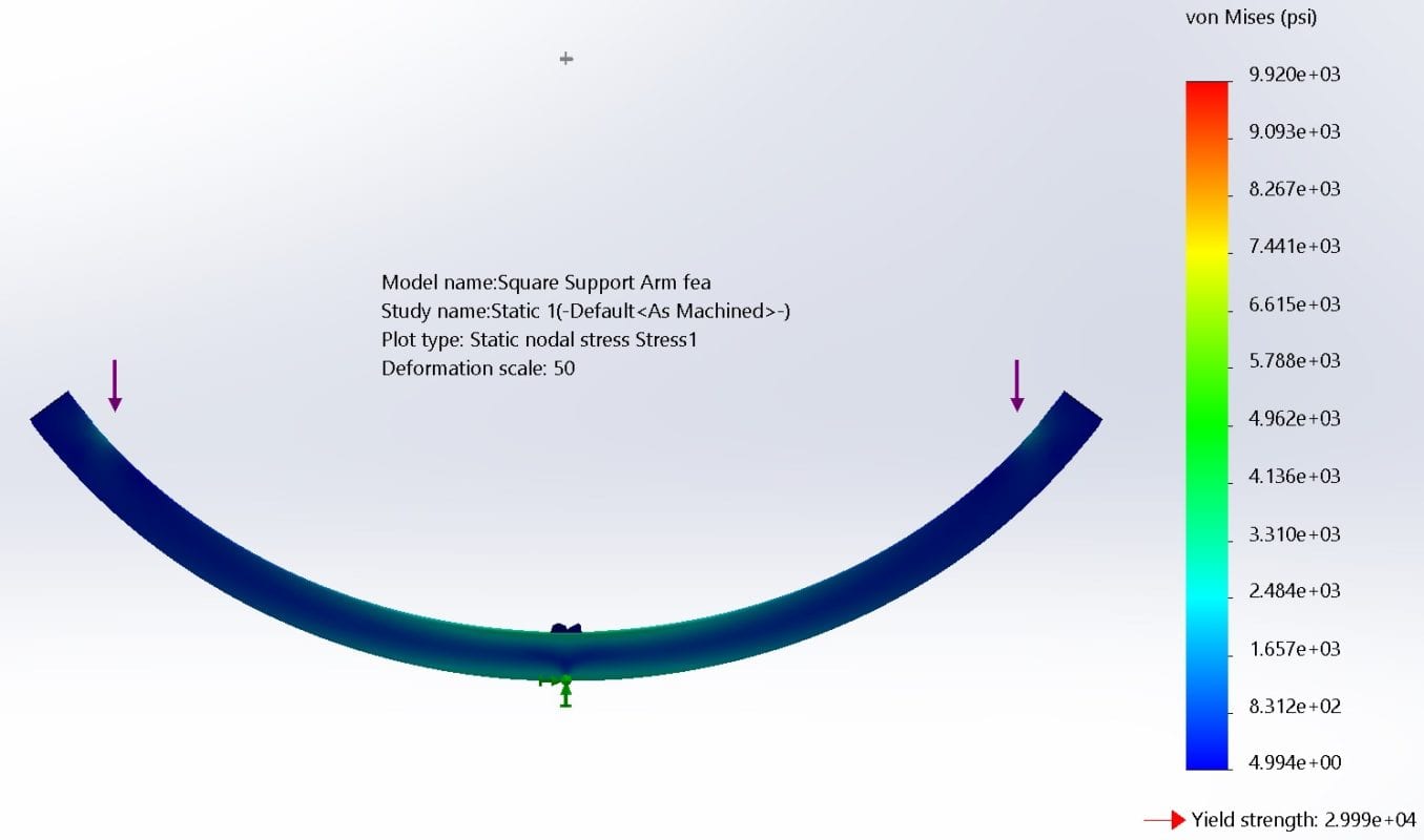
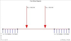
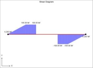
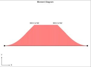
Support Arm Case:
100 lbf load acting vertically at the sling hook locations.
This simulates 1/3 of the maximum capacity (300 lb) acting on each support arm.
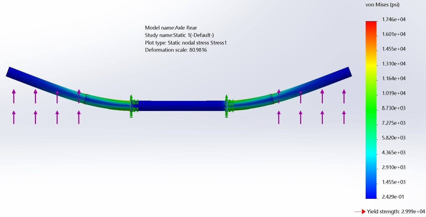
Rear Axle Case:
200 lbf total load distributed on the axle at the wheel hubs. The two fixed supports in the center represent the two welds on the axle.
Engineering analysis through the form of beam equations was completed to ensure correlations between the finite element studies and theoretical equations.
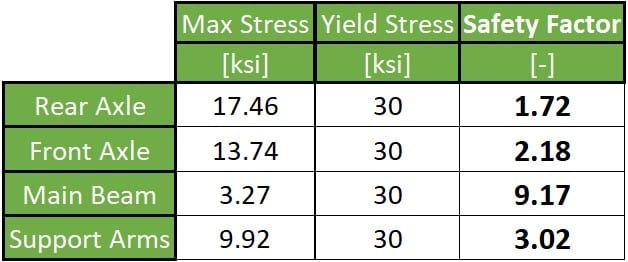
Von Mises (Distortion Energy) theory was used to calculate the Safety Factor of both axles, the main square beam, and the three support arms. Safety Factors for each are listed below:
Final Design
Specifications
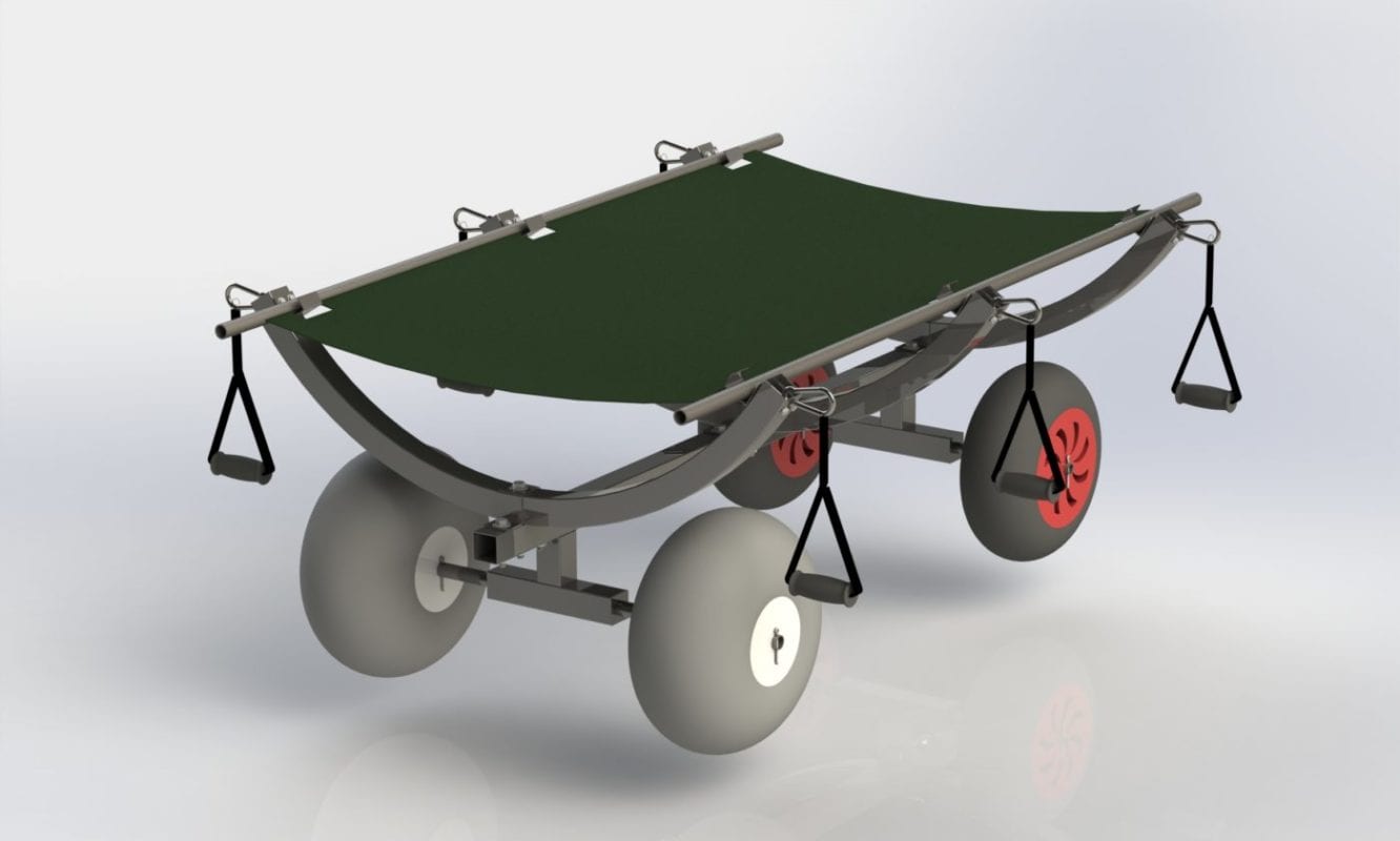
Weight: 62.1 lbs
Dimensions: 60” X 43” X 26.5”
Custom Components
- Stainless Steel Chassis
- Support Arms
- Support Arm Brackets
- Sling Hooks
Stock Components
- Wheels
- Handles
- Carabiners
- Fasteners
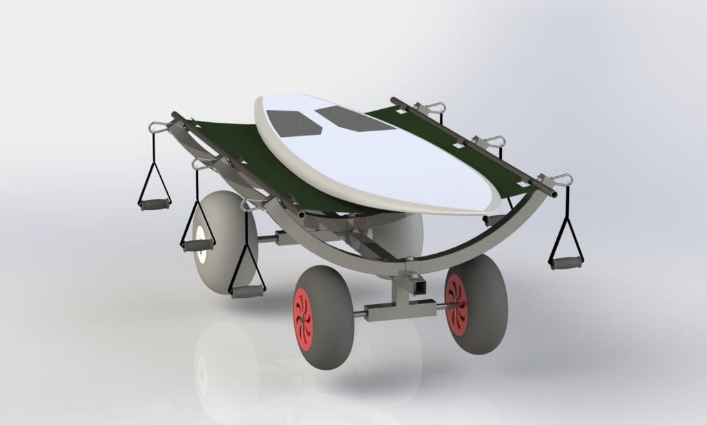
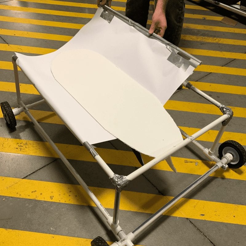
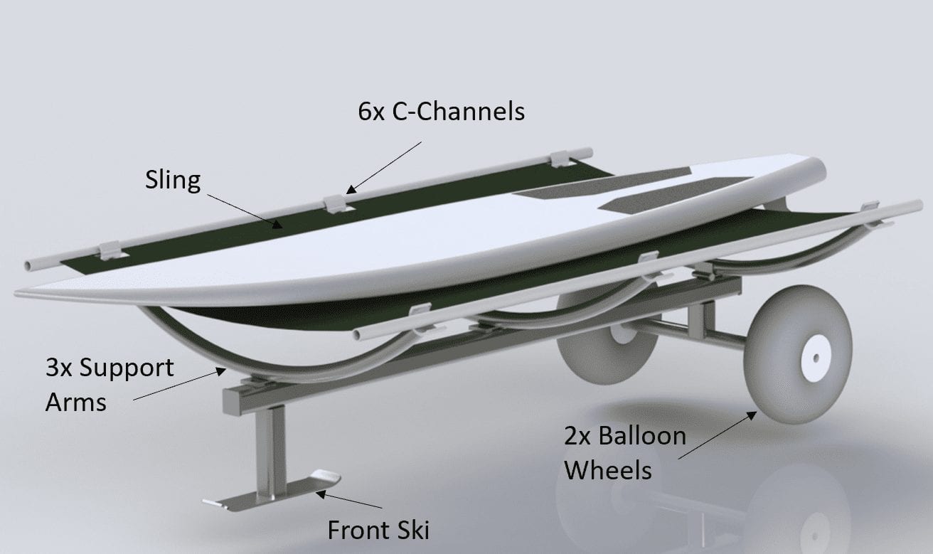
The focus of this final design is the Sling, which stretches between both ends of the Support Arms. By lying on top of this catamaran trampoline material with the fins hanging off the back end, it ensures there will be no damage to the underside of AmpSurf’s surfboards, which are normally a foam material.
When the user enters the water deep enough there will no longer be a load on the Sling, as the buoyancy of the board itself keeps it afloat. When the board begins to float one side of the Sling is detached from the hooks and allowed to drop, so that the surfboard and its user can exit off the front of the vehicle.
Testing
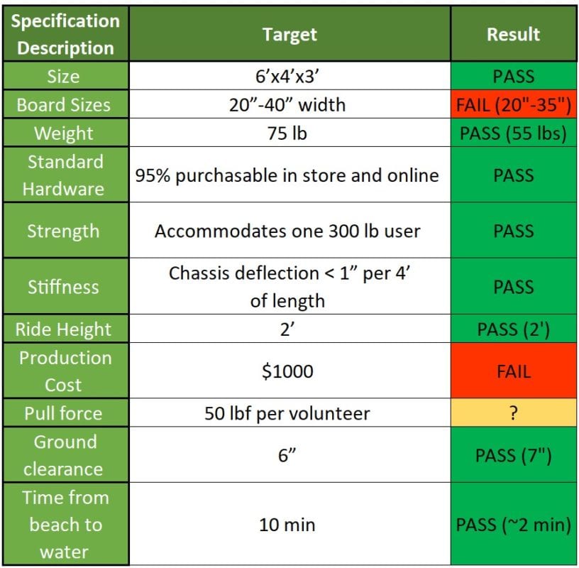
- The 40″ board width was failed by 5″ after a trade-off decision was made. If we had used Support Arms with a larger radius, it would’ve caused the ride height requirement to fail the target, which we found to be more important.
- The four core items of our design that are irreplaceable (Wheels, Support Arms, and Sling) went over the budget by itself. After discussing this with our sponsor we secured an increase in funds.
- Due to COVID-19, the pull force test was never able to be conducted.
Summary
- Along with every other group, the Covid-19 epidemic greatly affected our ability to finish our manufacturing and testing.
- The largest effect the epidemic had on our project was the ability to procure the Sling. As soon as businesses in San Luis Obispo can open back up, the QL+ club members will fit the sling so that the product can be used by AmpSurf as soon as possible.
- The epidemic also affected our ability to complete multiple tests, like the three-point bend test on our Chassis and the pull-force test with the final product on the beach.

