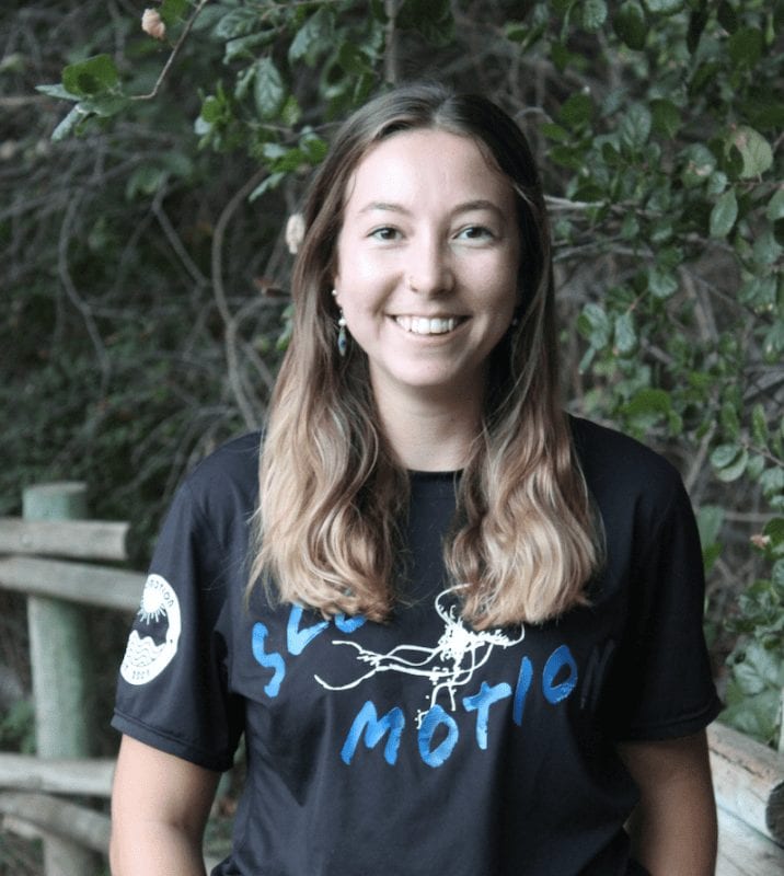
Frances Belcher
Mechanical Subteam

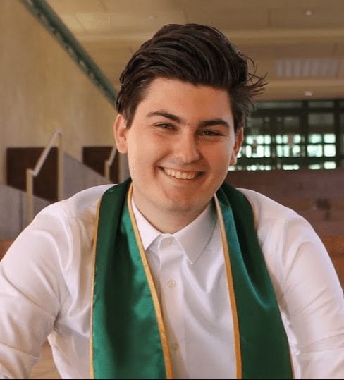
Matthew Hoffman
Mechanical subteam
Alex Petrov
Electrical Subteam
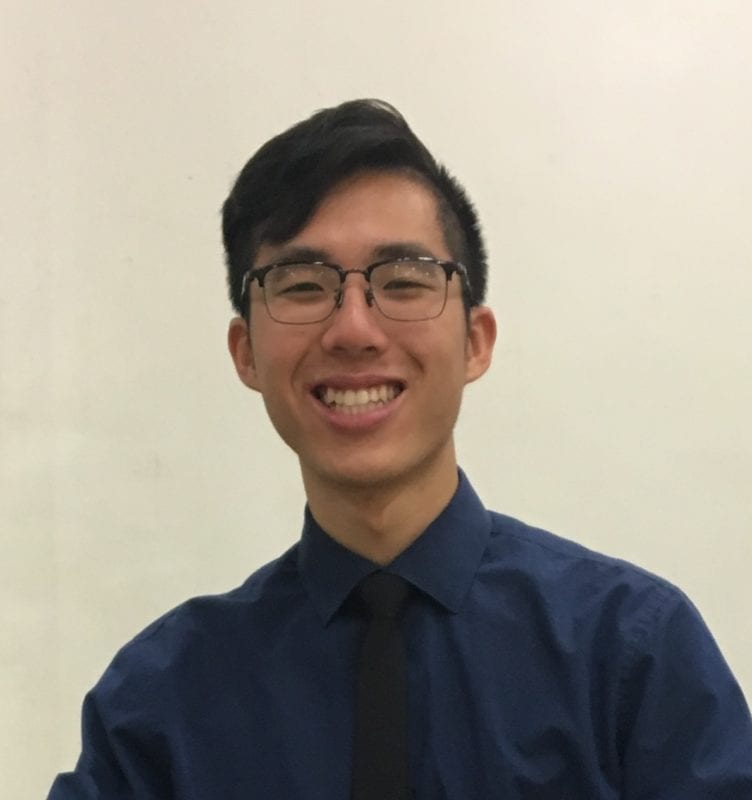
Michael Yiu
ELECTRICAL SUBTEAM

Robert Luttrell
ELECTRICAL SUBTEAM

Dr. John Chen
This project is sponsored by Dr. John Chen and the Mechanical Engineering department at Cal Poly!
