Carolyn is a fourth year Mechanical Engineering student with a general concentration. After graduation, she intends to work full time. She had an internship with SRAM as a design engineer and will be interning with Kiewit for the summer of 2021, as a quality engineer. She enjoys mountain biking, trail running, skiing, and surfing in her free time.
Daniel Coleman
Daniel is a fourth year Mechanical Engineering student with a concentration in Mechatronics. After graduation, he will be working full time as a design engineer at General Atomics. While at Cal Poly, he has been involved with Baja SAE, designing and building off road race vehicles. He enjoys everything outdoors, including biking, hiking, camping, and running.
Sebin Cho
Sebin is a fourth year Mechanical Engineering major and a peer health educator. This next coming school year she will continue her involvement in Cal Poly Health and Wellbeing as a peer coach. Sebin enjoys swimming and rollerblading during her free time.
Farhan Khan
Farhan is from Fremont, California. He enjoys the outdoors, backpacking, motorcycling, and old movies. He loves reading about physics and history and plans to work at Siemens after graduation. He chose the Adapted Tricycle project because of its real, tangible impact on the happiness and quality of life of another person.
Acknowledgements
We would like to first thank California Children’s Services and Linda Wolff for sponsoring this project. We would also like to thank our project advisor, Sarah Harding, for all of her help guiding us through the design process. Finally, thank you to CP Connect for providing us with extra funding. Our project would not have been possible without them all!
Our Project's Video
The following video gives an overview of our project including details about our final design, the design process, and recommendations for the future.
Our Project's Digital Poster
Project Goal
Everyone should be able to enjoy riding a bike
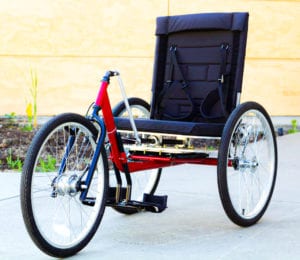
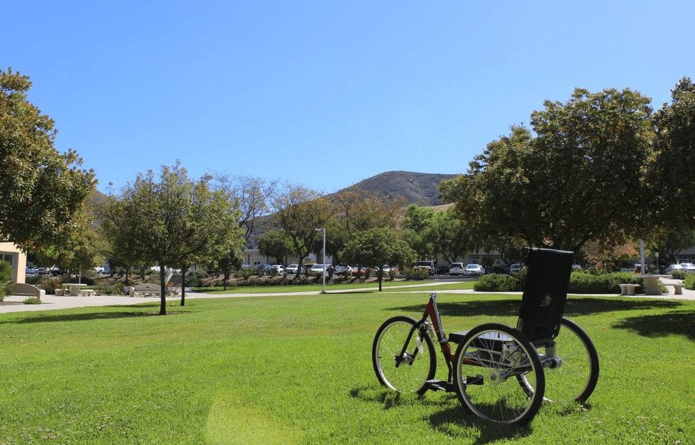
Our goal was to design a tricycle for Savannah. Savannah has Arthrogryposis, meaning she has limited mobility in her arms and legs. By creating a tricycle that is able to be powered, slowed, and steered using only her core power, she would be able to enjoy the freedom of riding a tricycle. California Children’s Services gave us a tricycle – the Invacare Top End Excelerator – but Savannah was unable to use it due to the arm power required to move it forwards. Using this tricycle as a base, we modified the design and ultimately created a tricycle Savannah was able to ride.
Specifications
Braking, propulsion, and steering must all be accomplished using the core muscles
Tricycle must be able to be maintained by a local bike shop
Tricycle must be comfortable and aesthetically pleasing
Tricycle must be safe
Concept Design
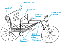
Concept prototype sketch using a push bar for power, rigid front axle steering, and pull brake.
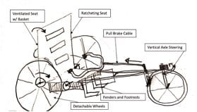
Concept prototype sketch using ratcheting seat for power, rigid front axle steering, and pull brake cable.
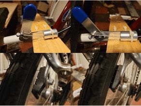
Concept prototype of braking system. This system models leaning back in the seat to slow the tricycle. The silver lever models the seat back. We decided to use this sub-system design.
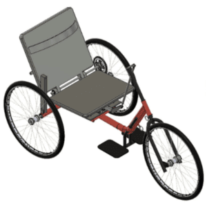
Model of the design we decided to move forward with. It uses a combination of the concept prototype ideas. It includes a ratcheting seat for power, leaning back to brake, and leaning side to side with a single steering member to turn.
Analysis
We completed a variety of calculations in MATLAB, Excel, and by hand to verify that our design would work. Calculations included gear ratio analysis, force on the steering member, turning radius, bearing life, etc. Below are some of the results from our analysis.
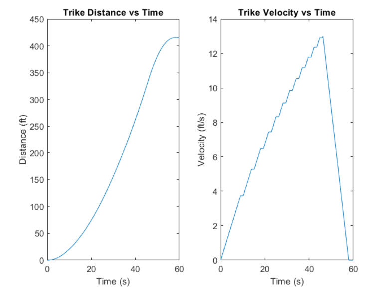
The speed and braking analysis was done in MATLAB. The figures above show how quickly and how far we predicted the tricycle would go in a given amount of time. This is how we determined our gear ratio of 26:16, and how we were able to be confident the tricycle would stop in a safe amount of time.
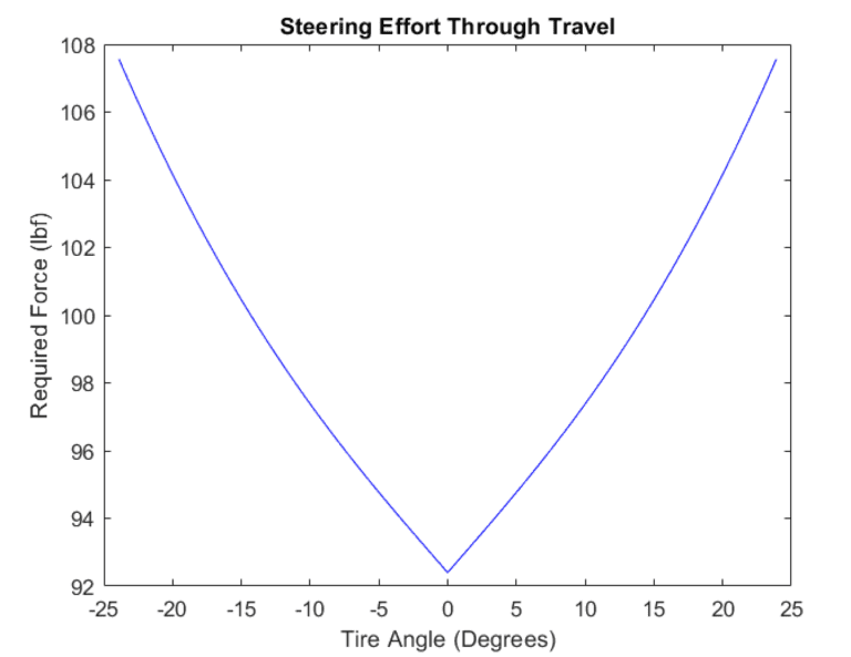
The steering analysis was completed in MATLAB. The figure above shows how much force would be needed on the seat to turn the front tire a given number of degrees. This analysis allowed us to verify that our steering system would work, and the force needed would not be too excessive.
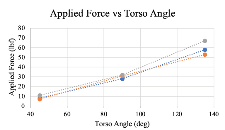
The torso force analysis was done using a bathroom scale, and the plot was generated using Excel. We wanted to make sure that the force needed to power and slow the tricycle would not be too high, even if the user is not sitting at 90 degrees.
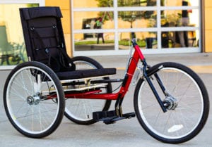
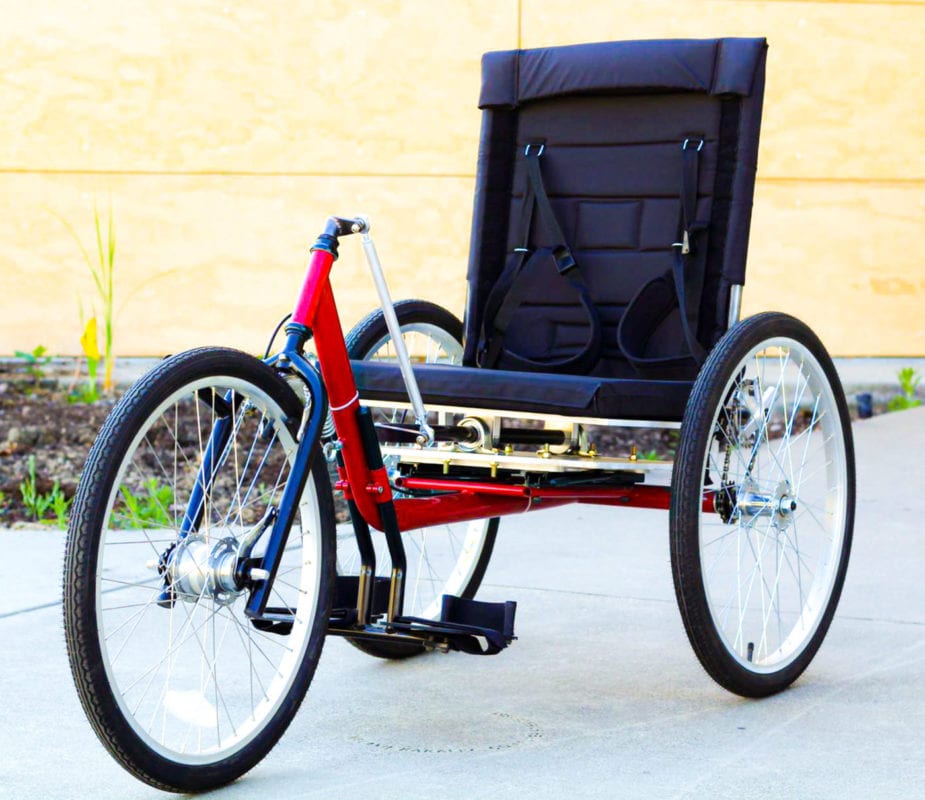
Final Design
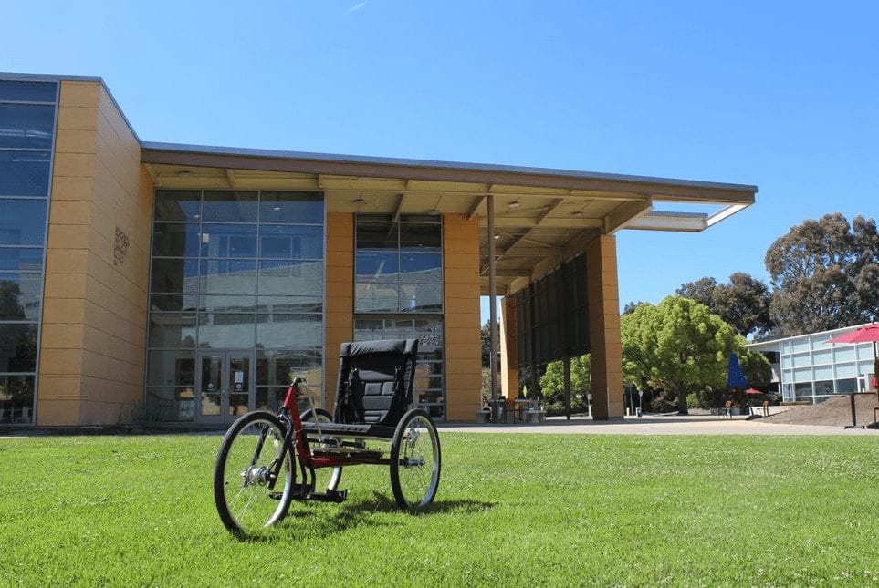
Our final design consists of three sub-systems: power, steering, and braking. Each sub-system is powered using only the core. Using the frame given to us as our base, our team created each subsystem making parts from scratch, modifying some purchased parts, and using a few purchased parts as is. The complete tricycle is pictured above.
Power Sub-System
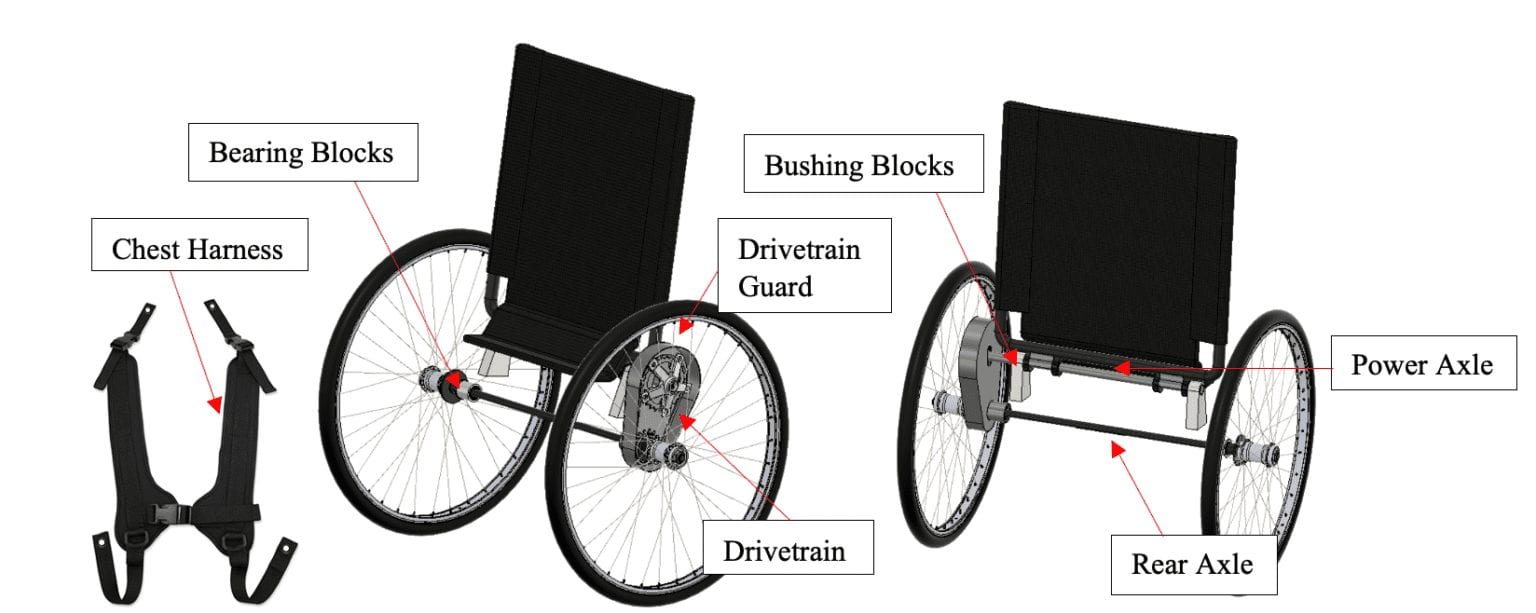
A breakdown of our power system is shown in the image to the left. The chest harness is secured to the back of the seat. When the user leans forward, the seat back turns the power axle, which moves the drivetrain, and the free-wheel of the drivetrain turns the power axle to propel the tricycle forward.
Steering Sub-System
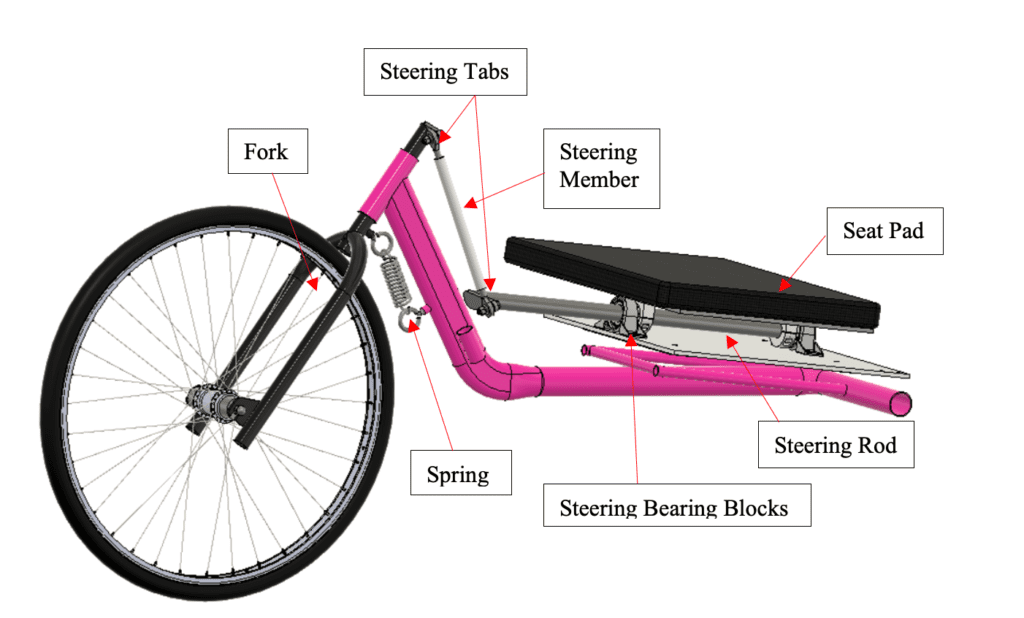
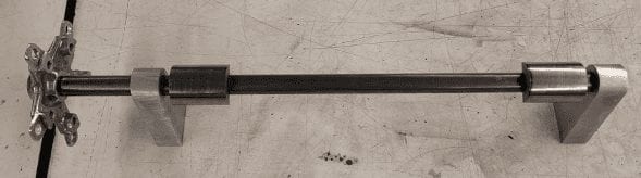
A breakdown of our steering system is seen in the figure to the left. The system consists of a double layered seat. When the user leans from side to side in the seat, the tricycle turns. The side to side movement of the seat turns the steering rod. The steering rod moves the steering tabs and steering member, which turns the fork. The spring ensure the turning radius is not too drastic, and the tricycle moves in a straight line when needed.
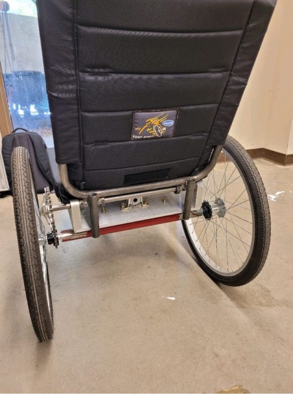
Braking Sub-System
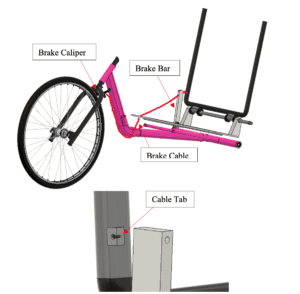
A breakdown of our braking system is seen in the image to the left. To slow the tricycle, the user leans back slightly in the seat. The brake cable is routed through the brake bar, and secured on the seat back using the cable tab. When the seat back is pushed backwards, the cable becomes taught and engages the brake caliper. The cable is secured at multiple locations along the tricycle to ensure it is not in the way. A hard stop was added to the lower seat back to ensure there is not extensive force on the cable when the user is not using the brakes.
Manufacturing
Process
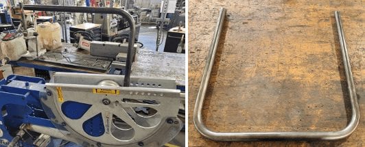
Bending the steel tubing for our seat back
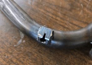
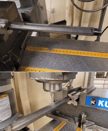
Many components for the tricycle were manufactured from raw material. Our team worked in the Cal Poly machine shops – Mustang 60 and the Aero Hangar – to complete the parts. We drilled, milled, sawed, sanded, bent, and welded the different parts for the tricycle. Additionally, a Cal Poly shop technician used a water jet to cut the steel plates for our seat, and a Baja SAE welder completed some of our welds. The bending process of the steel tubing for the seat back is shown above, and the milling for the keyway on the power axle is seen below.
Milling the keyway into the power axle
Components and assembly
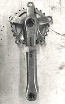
Crank arm modification for use in our drivetrain
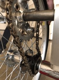
There are many different components included on the tricycle. Most of our components were purchased as raw material and manufactured, but some of the components were modified from purchased parts – such as the crank arm shown above. We were also able to purchase some parts for the tricycle without modifying them – such as the freewheel in our drivetrain shown below – and the frame of the tricycle.
Drivetrain of the tricycle
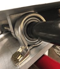
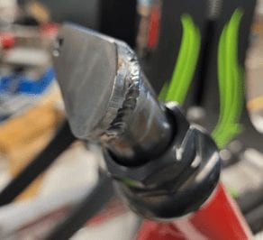
After all parts were complete, we assembled the tricycle. Most of our assembly was using basic fastners and press fitting bearings. We also welded to secure many components of the tricycle together. An example is shown below on a steering tab welded to the fork.
Steering tab welded to fork
Testing
We performed multiple tests to ensure our design was safe and functioned well. All tests were performed using our team members. All of our tests stem from the analysis we completed. A brief description of the main tests and the results are given below.
Test Descriptions
Maximum Speed: We completed a test to see how fast we could get the tricycle to go. This would tell us if we chose a good gear ratio, if our brakes would be sufficient, and ensure safety of the rider.
Braking Distance: We completed a test to ensure the brakes worked and the tricycle would stop in a safe distance.
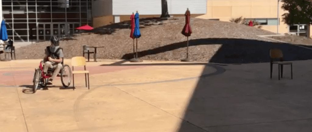
Turning Radius: We did a test to see how tightly we could get the tricycle to turn. This would tell us more about how the tricycle would perform and ensure there are no safety issues.
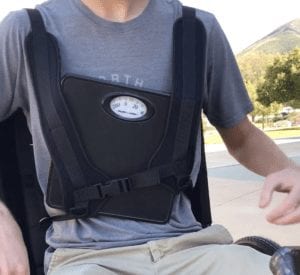
Maximum Push Force: We did a test to see how much force it would take to start moving the tricycle. This was to verify the user would be able to move the tricycle, and the force required was reasonable.
Chest Harness Comfort: We made sure the chest harness was comfortable and durable. Since it has the most contact with the user, it is important that it fits and works well.
Maximum push force test. Scale secured in between harness and rider. Tested the maximum core force needed to start movement of the tricycle.
Turning radius test. Chairs were placed various distances apart, and team members rode around them. When we were unable to complete the turn next to the chairs, we knew we hit the radius minimum.
results
Maximum Speed: The tricycle did not meet our speed expectations of 13ft/s +/- 3 ft/s, instead, it was slightly slower. This was not detrimental to our design or the safety of the rider. It is important to note for the user, and it is also something that should be considered for the future. Experimenting more with the drivetrain gear ratio would help solve the issue.
Braking Distance: The tricycle exceeded our expectations in the braking distance test. On average, the tricycle safely slows and stops in 8 ft or less.
Turning Radius: The tricycle exceeded our expectations in the turning radius test. The tricycle has a turning radius of about 7 to 10 ft.
Maximum Push Force: The tricycle did not meet our push force expectations. It was harder to start moving the tricycle than we thought. However, when we met with Savannah, she was able to start moving it, and she said we did not need to change anything. This test also does not compromise the safety of the rider. Experimenting with the drivetrain gear ratio would also help solve this issue.
Chest Harness Comfort: The harness was comfortable enough and worked to propel the tricycle. However, other designs should be explored.
Key Takeaways
Time management: Throughout the project there were many deadlines, and to meet these deadlines, we had to work through many difficulties and budget our time wisely. We learned the importance of staying organized and planning ahead.
Team work: Over the course of the 9 month project, we got to work with the same team, and we all learned how to work together and work through obstacles.
Design process: We started this project from scratch and worked through the entire design process. We learned how ideas are created, evaluated, organized, tested, and eventually how the final product comes to be.
Manufacturing processes: Many different manufacturing processes were required to build the tricycle. Some of our teammates learned how to use different tools in the shop, and some of our team members learned how to weld.
Recommendations for the Future
If we had more time to continue working on the tricycle, or if anyone wants to try and complete one that is similar, we would recommend doing a few things differently:
Experiment with the gear ratio: We would have liked to have a bigger chainring that allowed for more forward motion. The tricycle was easy enough to power with the core, but it did not travel as fast as we hoped.
Save enough time to get the tricycle powder coated: Originally, we wanted to powder coat the frame of the tricycle, but to complete the necessary parts on time, we were unable to perform this task.
Experiment with harness design: While the harness works, we think it could work even better and be more comfortable. We would have liked to look at other harness designs.
Send an email to pschuste@calpoly.edu to be connected with the project team. Please include the title of the senior project you’re inquiring about in the subject line.
Interested in Sponsoring a Mechanical Engineering Senior Project?


