Our Team
We are a group of mountain bikers who were able to apply our experiences to the design of the Adjustable Headtube Angle Headset.

Ben Harper
Mechanical Engineer
As a mountain biker, completing this senior project was the perfect end to these four years. Designing, manufacturing, and testing a bike component that adds so much to the ride was incredibly gratifying. After interning at Edwards AFB the past summers, I will work for an aircraft manufacturer in Oregon.
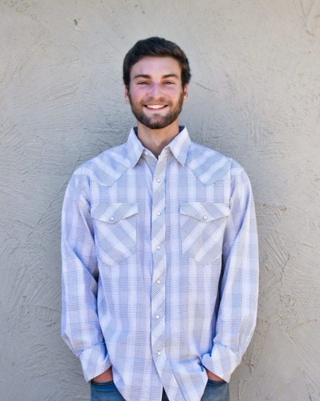
Josh Martin
Mechanical Engineer
I was a part of the SAE Formula club on campus, designing a racing seat and determining the new engine to put in the car. I spent the past few summers interning with an environmental construction company, operating heavy machinery and laboring. I will be interning with a small aerospace company in LA this summer. I love the outdoors, especially mountain biking, hiking and surfing.

Glenn Petersen
Mechanical Engineer
I am an avid member and President of Cal Poly Bike Builders. I have participated in the design and manufacturing of our club project builds, including a flat pedal and disc brake rotors. I also work as a Senior Shop Tech for the Cal Poly Machines Shops as well as the Safety Supervisor. This summer will be my second internship at Lawrence Livermore National Laboratory before I begin my Masters in Mechanical Engineering.

Dylan Prins
Mechanical Engineer
During my time at Cal Poly my interest in mountain biking has steadily increased and has concluded with a project we are all so stoked to share. During my time here I have shared involvement in Cal Poly Racing second and third year, as well as working in the Mechanical engineering department as a student safety technician. I will be returning to XL Construction this summer as an MEP Engineer Intern before finishing up my degree in the fall.
Acknowledgements
We would like to thank our senior project advisor and sponsor, Dr. Andrew Kean, for his idea and support throughout the project.
We would also like to thank Bike Builders for donated stock materials and access to tools.
Our Project's Video
Our Project's Digital Poster
Background
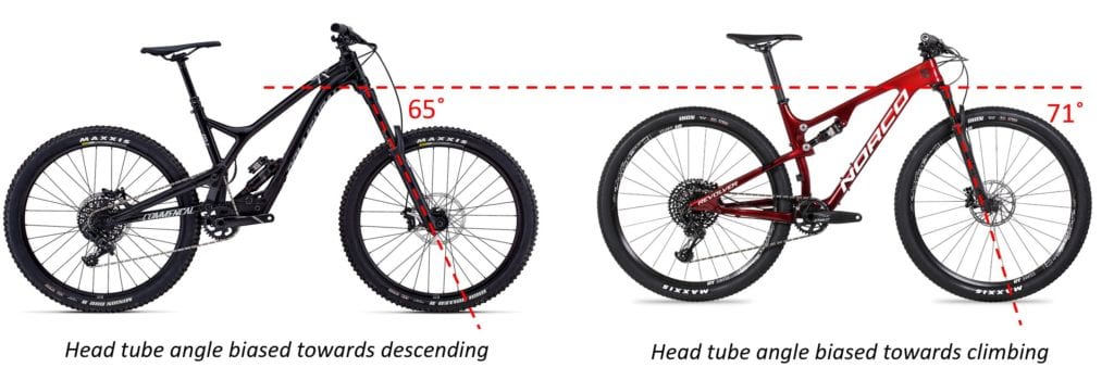
The most important factor in how a mountain bike handles is down to the frame geometry. The headtube angle is one of the most influential geometry characteristics and is normally defined by the bike manufacturer and cannot be changed all that easily, though small changes can have a large effect. A slacker angle such as the 65 degrees pictured above is suited for more downhill riding while the steeper 71 degree angle is suited for climbing. Our sponsor, Dr. Andrew Kean was interested in creating a product which allows for tool-less adjustment of this geometry parameter, trailside, in a manner of seconds.
Problem Definition
Avid mountain bikers who want to adjust their bikes’ geometry for climbing and descending need a device, compatible with existing frames, which allows easy and quick adjustment of the steering axis. This will improve the rider’s confidence and comfort by matching the bicycle’s handling characteristics to the trail conditions. This adjustability will reduce instability while climbing and descending.
Objectives
- Allow for adjustment of Steep, Neutral and Slack positions with a range of +/- 2 degrees from neutral.
- Weigh no more than 250 grams.
- Allow steering of 90 degrees right and left from straight ahead.
- Tool free adjustment in less than 20 seconds.
- Silent, dependable performance.
Concept Design
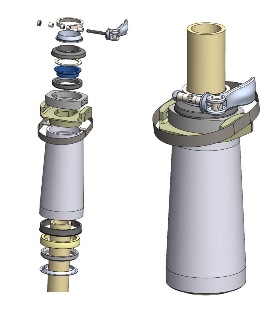
Pin positioning system was chosen for the following reasons:
- Tool free way of holding a position.
- Clamping mechanism to create sufficient friction is not required.
- Rotational degree of freedom still functions when different headtube lengths slightly change meshing geometry.
Other design choices to note:
- Cam handle and compression ring from One-Up allow tool free, quick application and release of preload needed on assembly, bypassing top cup bolt.
- Spherical bottom cup housing contact allows bottom of headtube to be a pivot like ball-in-socket. Allows angle change while supporting all axial forces.
Structural Prototype
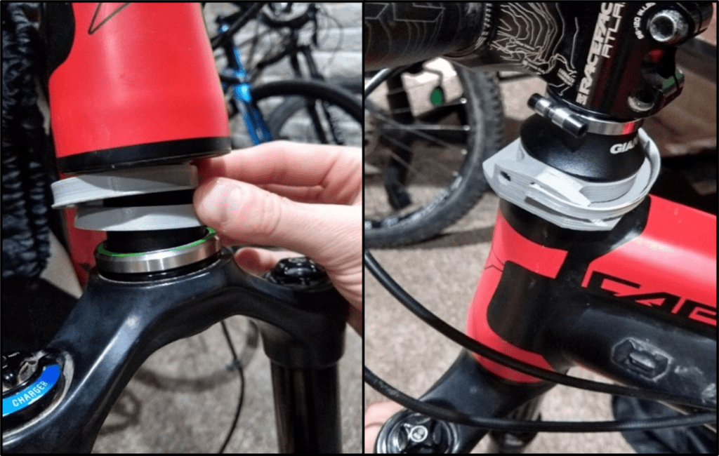
Before jumping right into creating our verufication prototype, we 3D printed a low cost version to check if our design so far could all fit on a bike and actually allow a change in headtube angle as expected. Results were positive so we continued forward and made some changes based on our observations.
Design Improvements
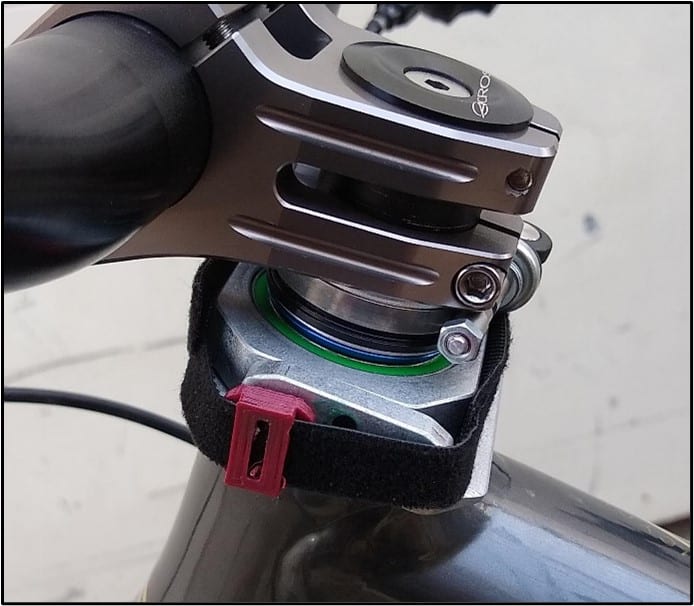
Moved to a Velcro pin retention system as steel band proved not flexible enough and too large.
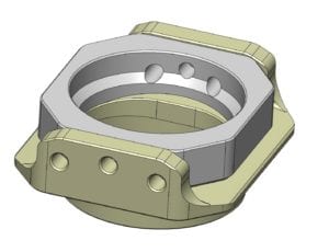
Filled out the top bearing housing to increase strength and increase manufacturability.
Final Design
LOading Case
Structural Analysis
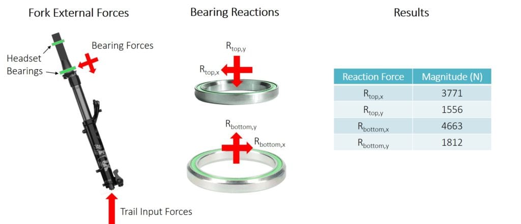
We determined a maximum loading case by taking a maximum normal trail force from a past study and calculating it back to what the top and bottom bearings will withstand. These were the forces our headset must take. The most important result is that the top cup assembly must withstand a force in the x-direction of 3771 newtons.
FUsion Analysis
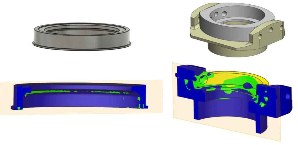
Ben employed Fusion to preliminarily test the top and bottom cup assemblies for structural soundness when withstanding our loading case prior to manufacturing. All results gave a factor of safety of 2 or greater so we were confident our design was strong enough for the application.

Specifications
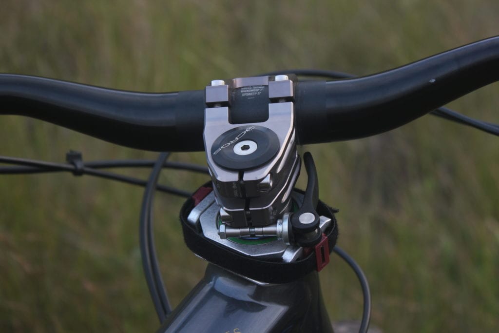
Mass -236 grams
3 positions: Steep, Slack and Neutral corresponding to -2, 0 and +2 degrees from original headtube angle.
Manufacturing
There are four main components that required heavy manufacturing: the top bearing housing, top cup, bottom cup, and bottom bearing housing. On the top side, a 3-axis CNC machine was used to manufacture all features in 4 operations (for both top bearing housing and top cup): top, bottom, and each pin-hole side. The bottom cup and bottom bearing housing were turned on a CNC lathe. Both started with internal features, then profile, and finally parting off.
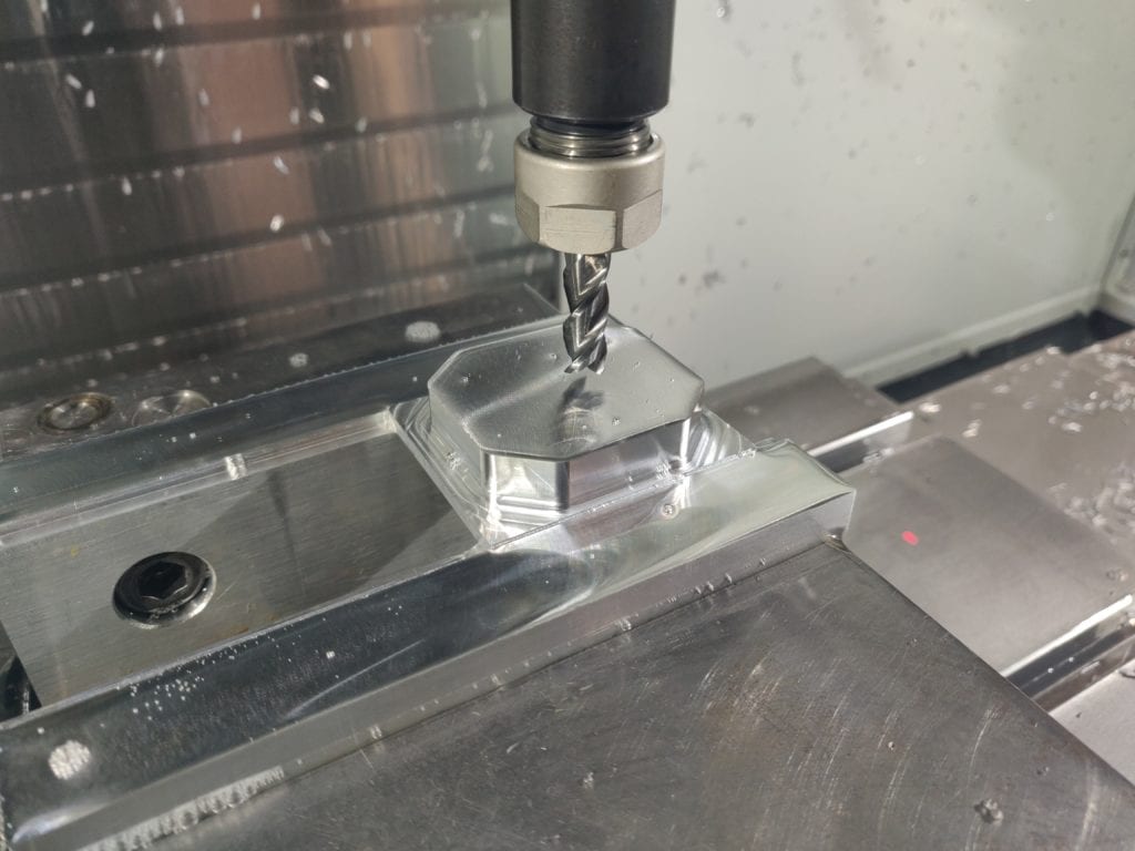
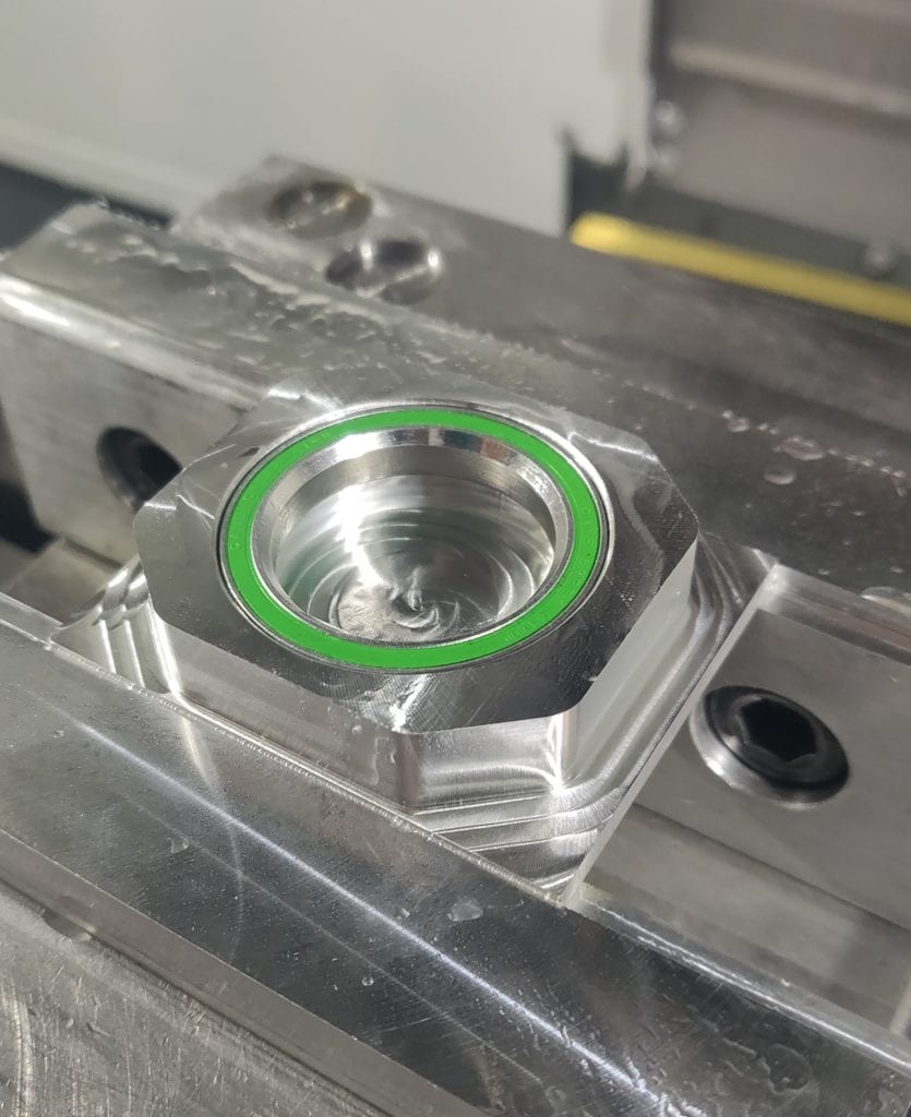
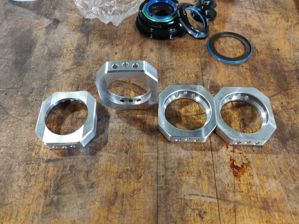
We manufactured 4 top bearing housings for Instron testing samples and test riding. A single top cup, bottom cup, and bottom bearing housing were manufactured due to limited machining resources available.
Testing
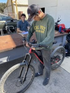
Adjustment Time- The adjustment time was tested by having each team member adjust from one position to another several times. An average of about 10 seconds resulted which is less than our target of 20 seconds.
Tools Needed to Adjust- During the previous test it was verified that no tools were needed to adjust the position of the headset.
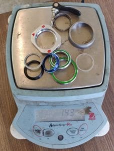
Weight- The total weight of our headset came out to 236 grams, well under our 250 gram target.
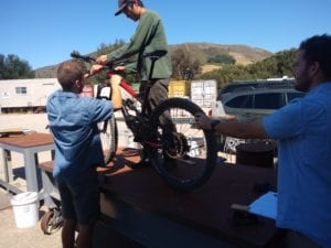
Range of Adjustability- It was verified that our headset allows 2 degrees of rotation of the steering assembly either way from the original headtube angle. With wheels on the ground this corresponds to a changed headtube angle of +/- 1.63 degrees from neutral due to the change in trim of the main frame during adjustment.
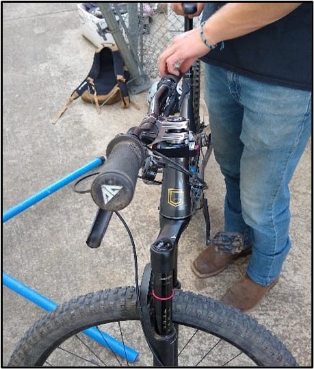
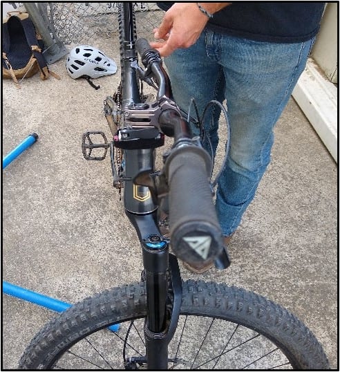
Rotation of Handlebars- It was verified that our headset allows more than 90 degrees of steering either way from straight on. Our headset does not affect steering performance.
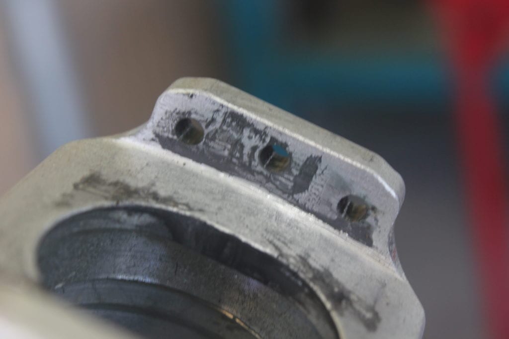
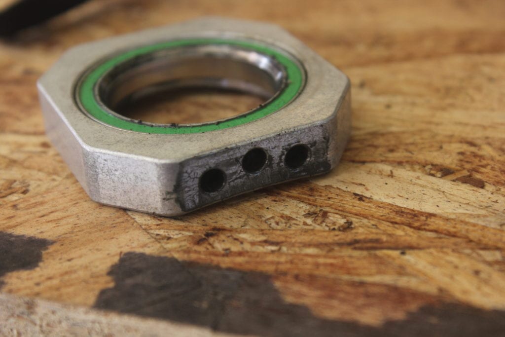
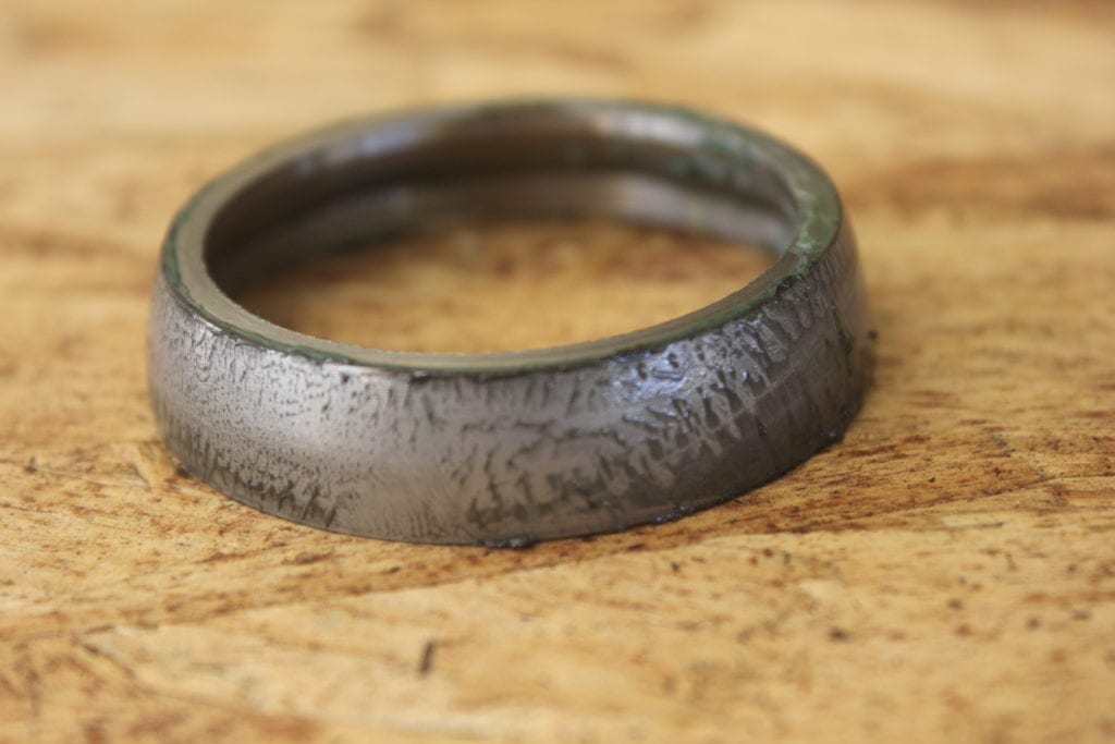
Maintenance Test- After the real world test rides, the headset was disassembled to verify the life and maintenance schedule of the product. With a lack of dust shield there was noticeable build of grime on the greased surfaces. However, CMM inspection of the top bearing housing indicated no statistical difference in pin-hole circularity or
Testing Continued
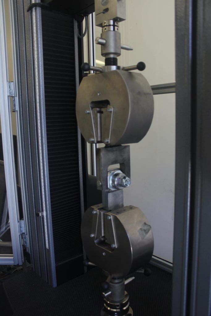
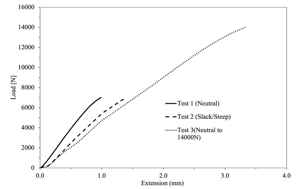
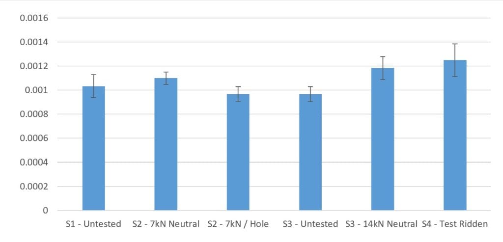
Load Test-To further test our headset, we devised an Instron loading test to statically load the weakest link of our headset, the top bearing housing and pins connection, to a maximum loading case of 7000 Newtons in the plane it would see during riding. The top bearing housing and pins withstood this force and even double it at 14000 newtons which bolstered our confidence in the design. Linear deformation rate in the Figure below confirms no plastic deformation occurred in any testing configuration.
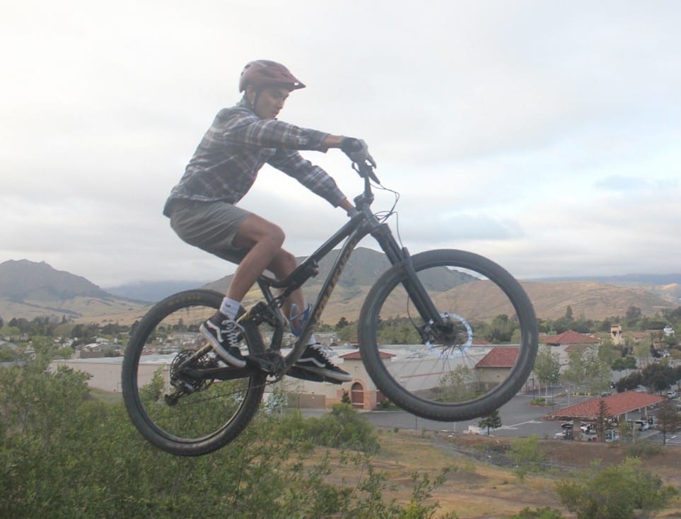
Real World Test Rides- After confidence was built that our design could withstand double the load we ever thought it might see, we installed the entire assembly on one of our mountain bikes and took it on trails around San Luis Obispo. The headset performed spectacularly with no problems through all conditions. The +/- 2 degrees of angular adjustment produces noticeable changes to handling.
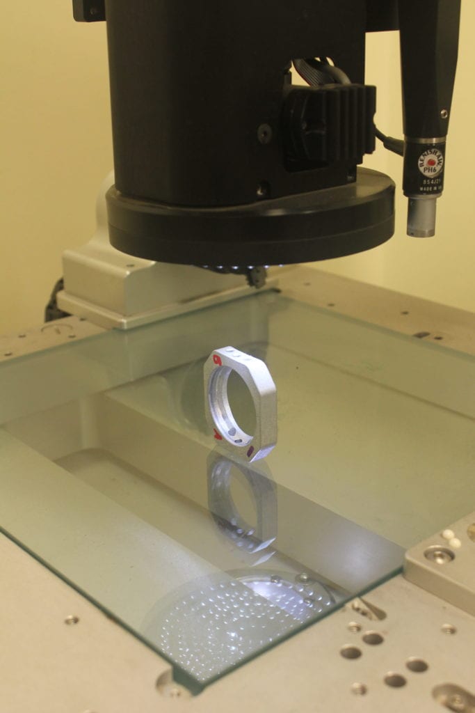
Experimental Results- We used an optical CMM (Micro-Vu Vertex) to measure the circularity of the pin holes to see if Instron testing and test riding impacted the part. Assuming uniformity between samples, a repeated measures ANOVA (Analysis of Variance), at 95% confidence, determined there was no statistical difference in circularity with different treatments. The bar chart below displays the average circularity of each sample with standard error bars. Sample 1 and Sample 3 were treated as controls. Sample 2 had a single loading event of 7kN in the neutral hole, as well as 7kN in the slack and steep holes. Sample 3 was also tested in a single 14kN loading in the neutral hole. Sample 4 was test ridden per Real World Test Riding procedures.
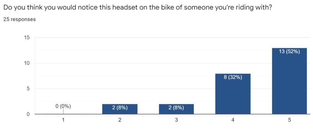
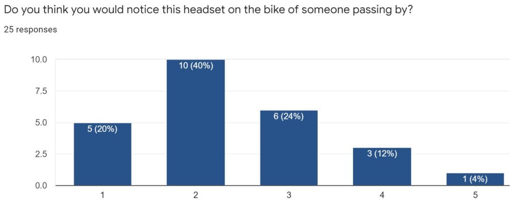
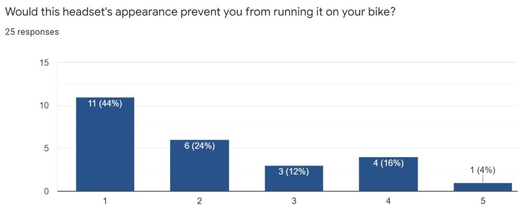
Public Response- We received 25 responses on our aesthetic survey where 5 indicates strong agreement and 1 indicates strong disagreement. Overall the design is noticeable but would not detract from someone desiring the performance it provides.
Recommended Work
Improvements to be made if product were to be re-designed:
- Redesign and manufacture bottom cup and bottom bearing housing to mesh well with shape of most forks which have an extension not accounted for in this iteration. Would help fork sit more flush in headtube and reduce stack height.
- Remanufacture top cup with rails extended and indents machined to hold Velcro away from top bearing housing and other moving parts.
- Improve pin retention system. Redesign the adjustment mechanism to improve operation and reduce adjustment time.
- Produce more complete assemblies to expand test riding regime to gain further insight into different riding styles affect. This would further provide data points in the analysis of wear and use. Gained insight into user perspective from a broader audience would also be gained.
- Design and manufacture a dust shield to fully protect against ingress of particles into top cup and top bearing housing .
