Our Team

Ryan Funchess
Controls Master
I am graduating fourth year mechanical engineering student with a concentration in Mechatronics. I am strongly interested in electromechanical design, stress analysis, and system modeling. After graduating, I am working as a mechanical engineer at Lawrence Livermore National Laboratory (LLNL) at their National Ignition Facility (NIF). Around San Luis Obispo, I enjoy hiking, going to the beach, and playing cards on a sunny day.

Nick de Simone
HARDWARE GURu
I am currently a fourth-year Mechanical Engineering student with a concentration in Mechatronics. I come from Long Beach, CA – which I have heard some refer to as “The Greatest City Ever Created” – and hope to return there for a career. As it stands, I am interested in automation and am working with Daring Engineering on a number of product development projects. I have really enjoyed working with this senior project team over the course of the year and am excited to hear of their undoubtedly remarkable career journeys.

Juan Marco Majano
SOLE POINT OF CONTACT
I am a senior mechanical engineering student, concentrating in manufacturing. I am interested in renewable energy technology, product design, computer hardware, and the automotive industry. In my pastime I enjoy playing, watching, and discussing the game of basketball. I am currently participating in a co-op at Applied Materials working in advanced energy storage team in the Office of the Chief Technology Officer organization. I love San Luis Obispo and I hope to retire here.

Caleb O'Gorman
fRONTEND Wizard
I decided to concentrate in mechatronics as I have always been interested in making the world more automated. Following graduation, I will spend the summer traveling and then start my career as a project engineer in San Diego. My favorite part of engineering is working with people to see a project from start to finish. On my leisure hours I enjoy surfing, playing sports, lifting weights, and eating well made sandwiches.
Acknowledgements
This project would not have been possible without the guidance of our incredibly dedicated coach, Professor Peter Schuster, or our generous sponsor, Simon Xing. We give our sincerest gratitude to them and the rest of the Cal Poly engineering department for such an invaluable learning experience.
We would also like to thank the Cal Poly machine shops and the shop techs for the world class facilities which have remained open to us, even in the face of extenuating circumstances.
Our Project's Videos
This video contains an overview of our project and summarizes the design process.
This video showcases our final prototype. Come see the feed drive in action!
Our Project's Digital Poster
Mission Statement
Develop an operational single axis CNC Feed Drive similar actuator for use in a future Cal Poly Controls Lab and for graduate-level system modeling.
Design Constraints
- 30 cm travel length
- 50 micron accuracy
- 5 kg payload
- System mass < 50lb
- $800 budget
- Accepts digital inputs
Drivetrain Analysis
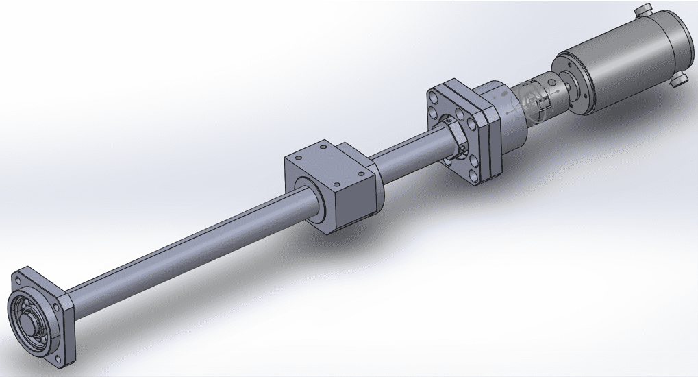
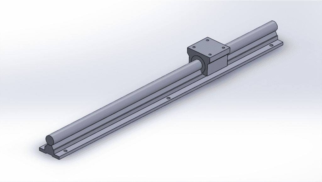
We opted to use a motor and ballscrew combination for the following reasons:
- It is industry standard and thus will provide a relevant learning experience
- Ballscrews maintain very high levels of precision
- Ballscrews are strong, durable, and can transmit large loads
- Low maintenance compared to belt drive or rack and pinion
Other considerations of the drivetrain design:
- Flexible shaft coupling, which allows for some axial deviation between motor shaft and ballscrew
- Thrust bearing, which is a fixed support that allows for ballscrew rotation and can absorb axial loads
- Driving design constraint was the ballscrew’s natural frequency, resulting in a thick ballscrew of 25cm diameter
- Rails with linear bearings provide vertical support to the load with low friction
Frame Design
PLA design
For our frame we initially wanted to go with PLA for its customizability, low price, and ease of prototyping.
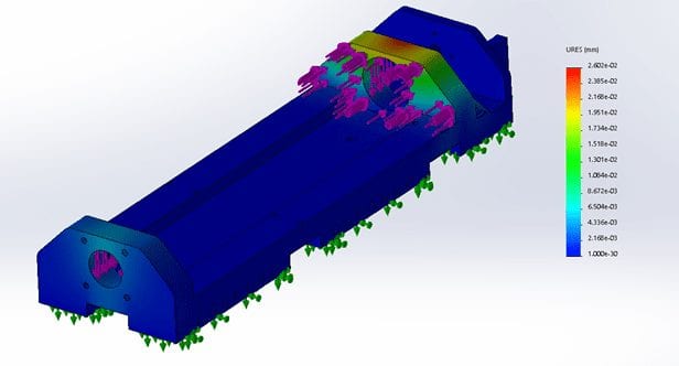
Subsequent FEA analysis showed that the PLA strength was sufficient but the large length and volume of the frame gave rise to 3-D printing complications.
ALUMINum design
We decided to pivot our frame design and selected to manufacture each face out of sheet metal aluminum and assemble them with non-permanent threaded fasteners.
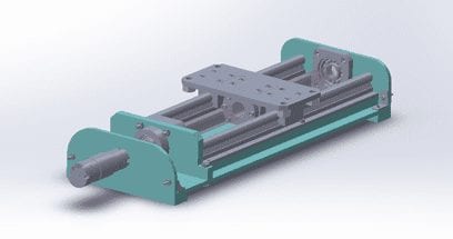
This CAD model allowed for accurate placement of components and dimensions of the faces to be finalized in order to begin manufacturing
This project is sponsored by Dr. Xing of the Cal Poly Mechanical Engineering Department
USER INTERFACE
Following Professor Xing’s recommendation, we decided to develop a graphical user interface using MATLAB App Designer. This GUI will allow students in the Controls Laboratory to interact with the Feed Drive and experiment with different controller gains while running the system in closed loop, and characterize the system experimentally while running the system in open loop.
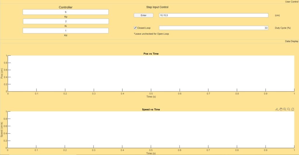
User Inputs
Controller: User can input controller gains for a PID controller that will be written over the serial port and implemented on the backend.
Step Input Control: User can input a series of three positions separated by a comma that the table will attempt to reach at steady state.
Open Loop/Duty Cycle: If the closed loop checkbox is unchecked, the system will run in open loop. If run in open loop, the user must also specify a duty cycle at which to run the motor.
Data collection
The data collection tab contains a plot of table position and table velocity as a function of time. The plots update in real time so that the user can watch the table move along with its digital position and velocity reading. After the data collection is complete, the positions, times, and velocities are exported to the MATLAB workspace where they can be saved and further analyzed later. This allows students to better characterize system gains, time constants, and analyze the effects of the PID controller that they will design.
Manufacturing
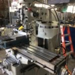
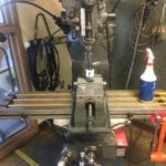
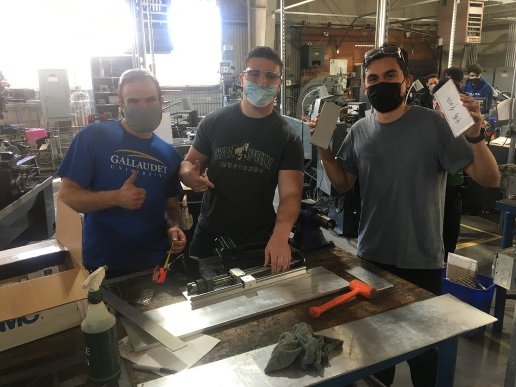
Manufacturing occurred primarily in the Cal Poly machine shops with some light assembly performed at the teammates’ houses. Nick and Juan were able to obtain their yellow tags and thus spearheaded the machining processes.
Software Implementation
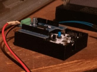
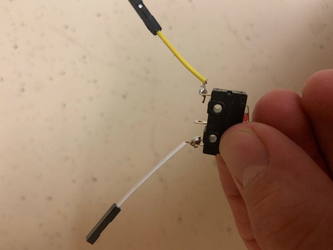
We decided to write our hardware drivers and task files in Python since we have prior experience in embedded Python software from the mechatronics courses. The entire backend code package consists of 4 class modules and a main.py.
Final Prototype
Specifications
Weight – 47 lbs
Maximum Speed – 7.5 cm/s
Travel Length – 25 cm
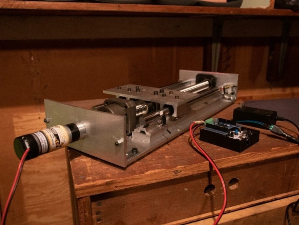
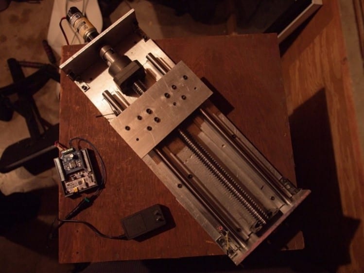
Custom Components
- Base Plate
- Datum Face
- Motor Face
- Ball Bearing Face
- Legs
- Wooden Base
- Linear Rails
- Metal Brackets
- Plate Masses
- Soldered Roller Switches
Stock Components
- Motor w/ Encoder
- Ballnut
- Ballnut Bracket
- Thrust Bearing
- Ball Bearing
- 12 V Power Supply
- Nucleo MCU
- Motor Driver
- Flexible Shaft Coupling
- Fasteners
The prototype and all of it’s software was delivered to Professor Xing on June 3rd, 2021. Hopefully we will see it in the Controls Laboratory soon!
Design Verification
User Interface Test: For this test we recruited three new subjects to test the MATLAB GUI. None of the testers had prior experience designing controllers but were each given a brief explanation on how to operate the app. We found the average time for the users to complete a run was 29s
Travel Speed Test: For this test we ran the system in closed loop to an arbitrary three points and then, by observation, determined the maximum speed from the velocity vs time plot. The maximum speed was determined to be 7.5 cm/s.
Recommendations
We have several recommendations that we believe will improve the system’s performance if implemented in future iterations:
- Source a more powerful motor that could provide a greater torque and a greater speed.
- Purchase higher quality bearings to decrease static and kinetic friction in the drivetrain.
- Replace mechanical limit switches with a similar device that has a greater degree of stiffness so as to reduce overshoot error in the zeroing function.
- Manufacture frame with a CNC mill to decrease tolerances and further prevent binding possibilities.
- Better organize wiring and other electrical components to improve aesthetics and system longevity.

