
Michelle Chandler

Jacob Nelson

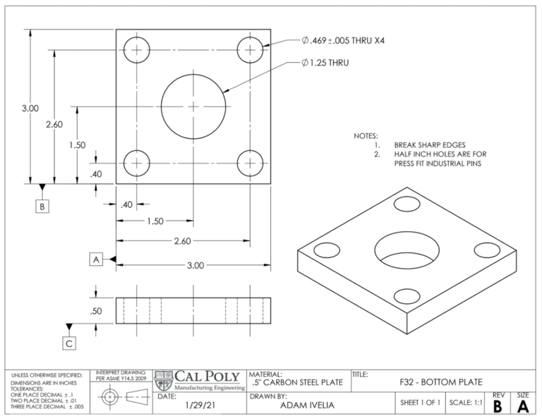
Adam Ivelia

Quang Truong

Blueline Robotics
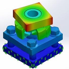
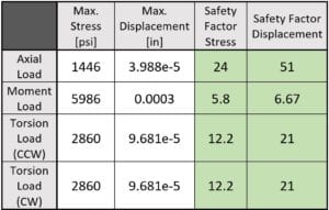
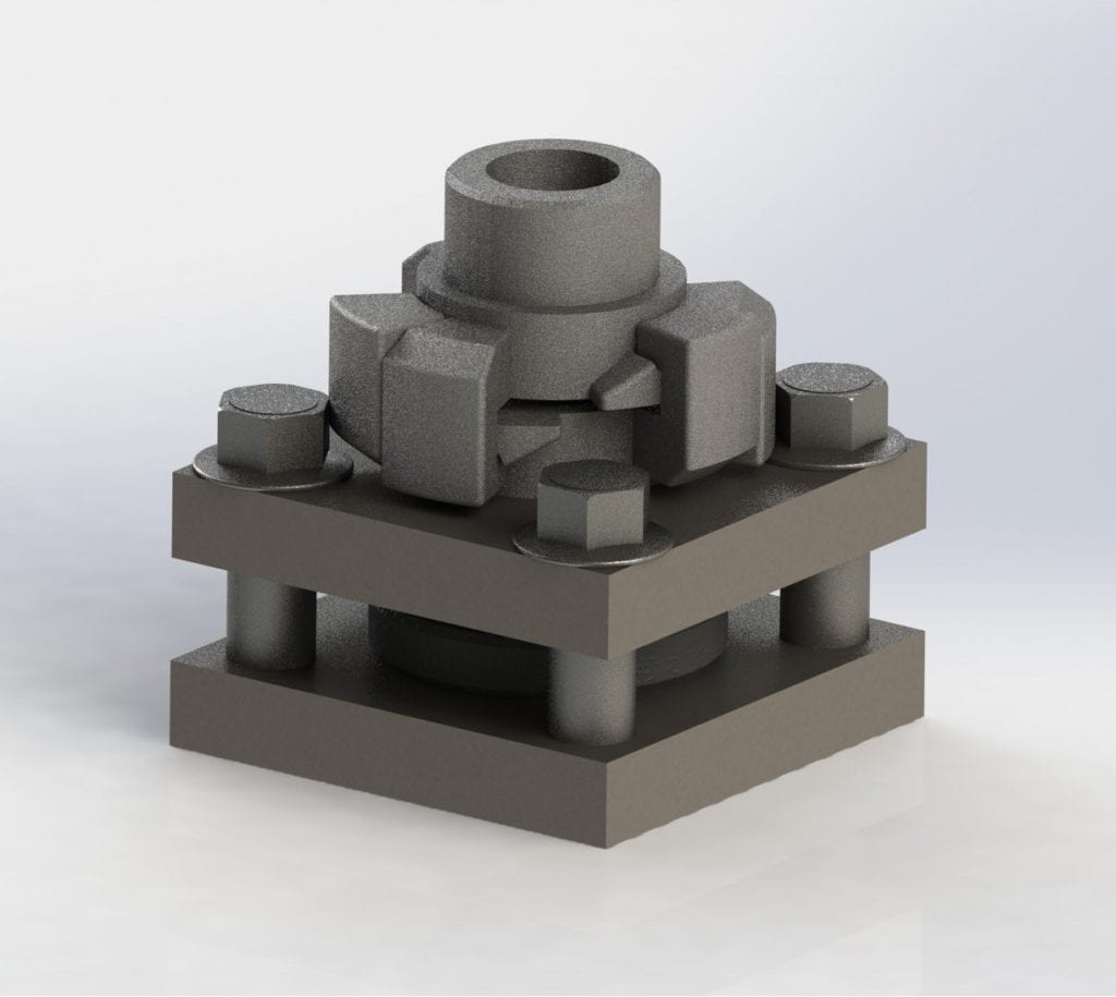
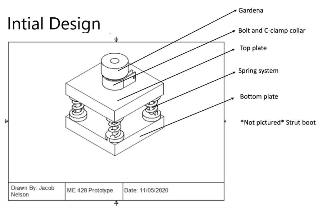
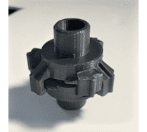
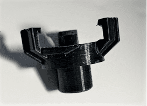
Finite Element Analysis (FEA) was completed on the design with focus on the bayonet locking mechanism, the top and bottom plates, and the industrial pins. This testing was completed using SolidWorks. The passing criteria for this test was as follows:
- The maximum displacement of the parts should not exceed .002mm.
- The safety factor for the material strengths should be no less than 5.
Three different load conditions were tested:
- Cantilevered load accelerating horizontally and vertically at 2 radians per second.
- The impact force of the robot tipping over onto the arm attachment.
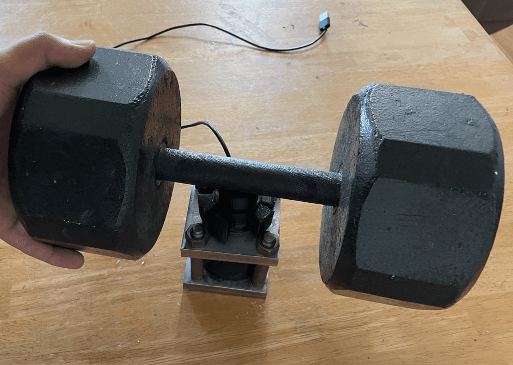
- The axial force of 50lbs on the system from heavy attachments.
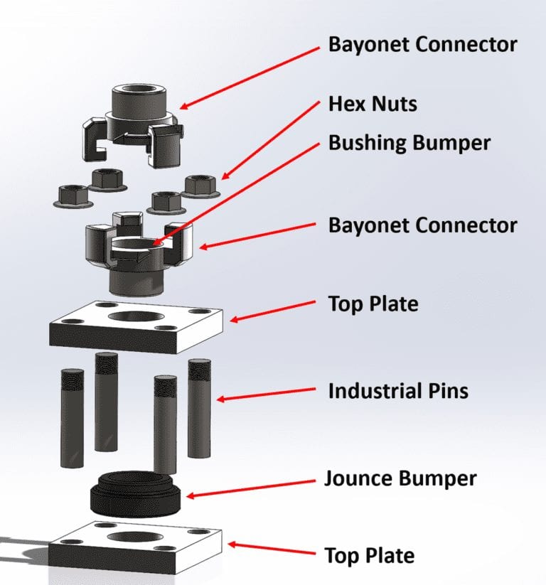
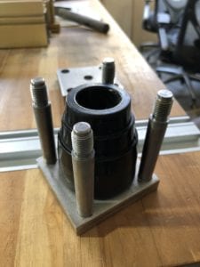
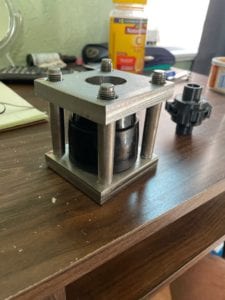
In a static study, the bottom plate was defined as fixed in the places it would be welded to the main robot chassis. A rectangular block was fixed over the top bayonet connector piece to simulate a miscellaneous attachment for the robot. The different load cases were then applied to this mock attachment piece.