Our Team

Benjamin Bons
Team Member
I am a 4th year mechanical engineering major. I have an interest in mechatronics, the biomedical industry, and in fluid dynamics, and I am continuing my studies in Fall 2021 for my Master’s degree at Cal Poly.

Sean Casteel
Team member
I am a 4th year mechanical engineer who has been working with BLDS for 2 years. I was largely responsible for 3D printing and CAD, and find the most satisfaction working with fluid mechanics. I am working for General Dynamics NASSCO in San Diego after graduation.

Hailey Earnest
Team Member
I am a 4th year mechanical engineering student. After graduation, I will be pursuing my Master’s degree in the Cal Poly Blended Program.

Biren Rama
Team member
I am a 4th year student interested in computational simulation, composites, and fluid dynamics. I mostly worked on the out-gassing process for the belt and developing the initial molding concept.
Our Project Video
Acknowledgements
Thank you to our sponsor, Dr. Westphal, for all of his cooperation and help throughout this project. We would also like to thank our advisor, Dr. Kean, for all of his support.
Our Project's Digital Poster
Project Purpose
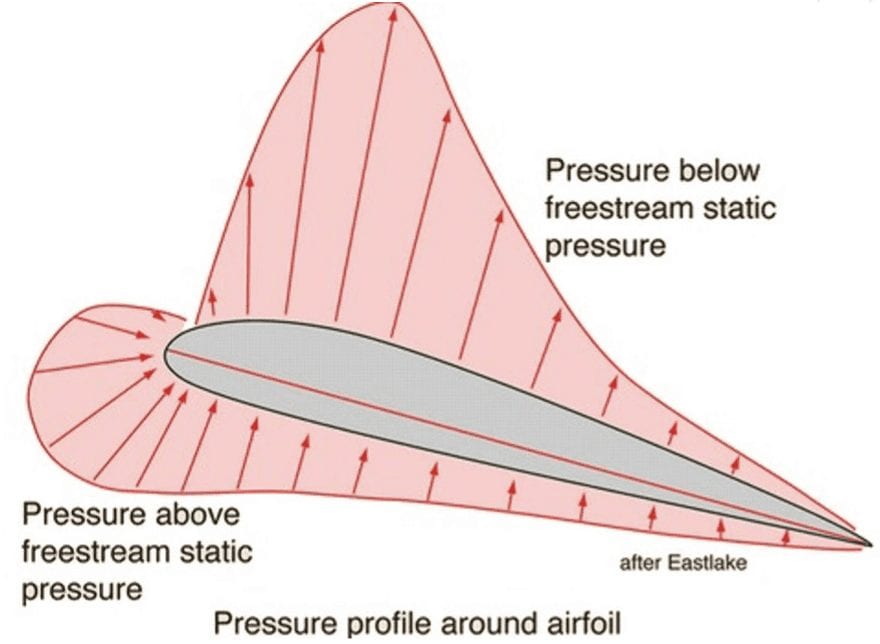
Our sponsor, Dr. Russell Westphal, uses his Boundary Layer Data System (BLDS) to take pressure measurements in aircraft flight tests. This system requires an attachment to capture the static pressure field on the surface of a body.
The device must be able to:
- Be manufactured easily, repeatedly, and reliably
- Minimally disrupt the flow of the airstream over the wing
- Attach to the wing of the aircraft easily
- Reliably measure pressure distributions
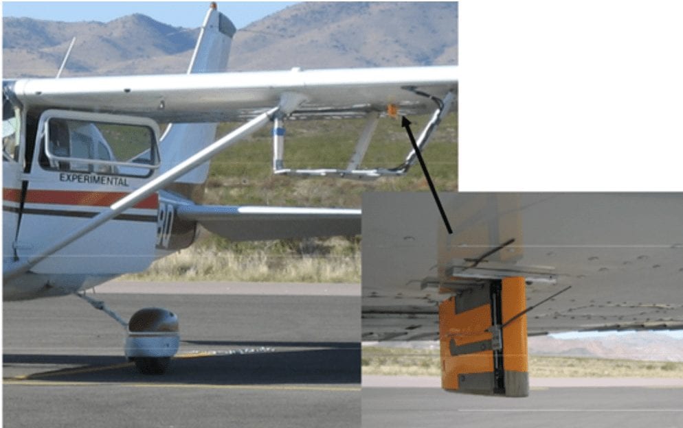
Photo of the BLDS (shown in orange) during a flight test.
Specifications
- Measure pressure distributions
- Connect to BLDS system
- Does not affect flow
- Flexible port placement
- 2” max width
- 0.15” max height
- 0.040” port size
- Variable number of ports
- Flexible material to allow wrapping around surface
Design Process
Preliminary Ideas:
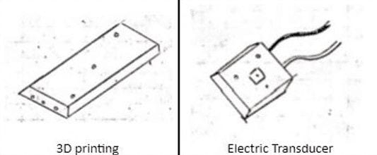
- Direct 3D printing
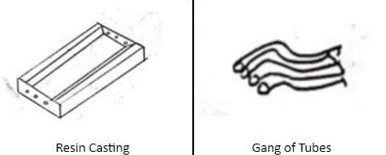
- 3D printed mold with silicone resin casting
- Electronic sensors
- Laser cut vias
- Strip-a-tube/Gang of tubes
Preliminary Testing & Analysis
Testing of laser cut vias from a rubber billet as well as direct 3D printing were completed, but both methods indicated flaws. Electronic sensors were proposed, but proved to be too expensive and awkward. Thus, these methods were not pursued further.
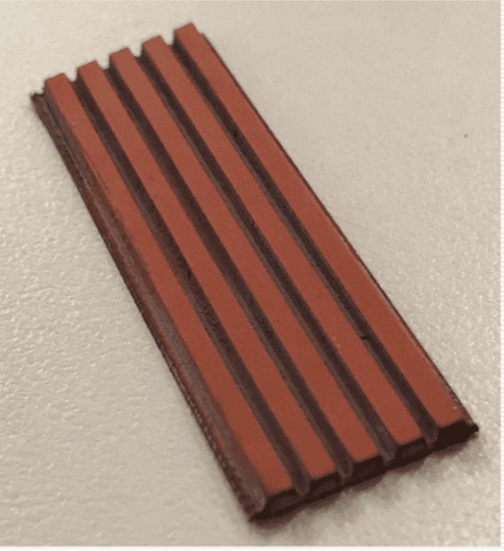
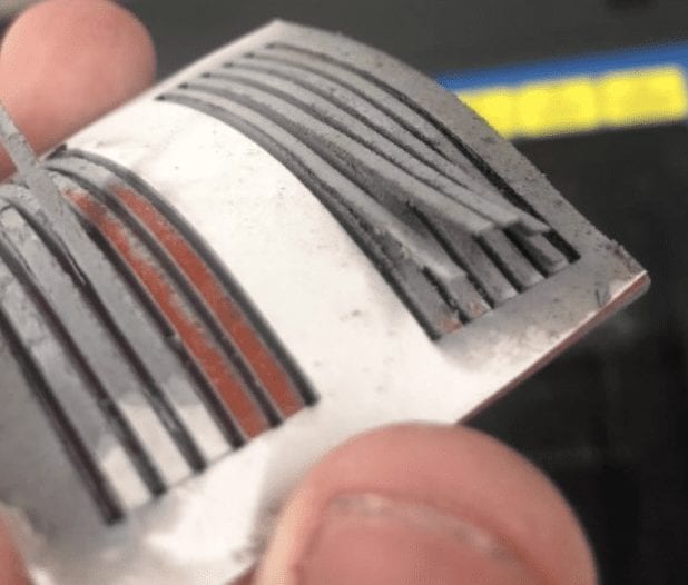
Laser cut vias with curling defect occurring on the adhesive backing.
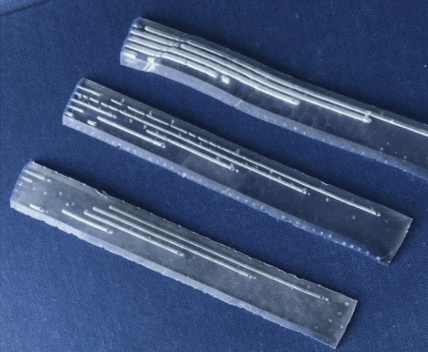
Previous iterations of 3D printing. The resolution of the print was too crude so unfortunately the vias collapsed.
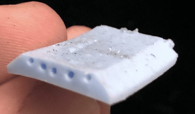
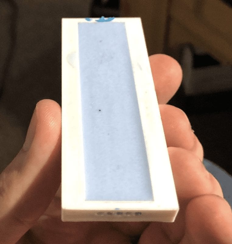
First iteration of the silicone cast belt with different sized cores for testing.
This project was sponsored by Bounday Layer Data System.
Final Design
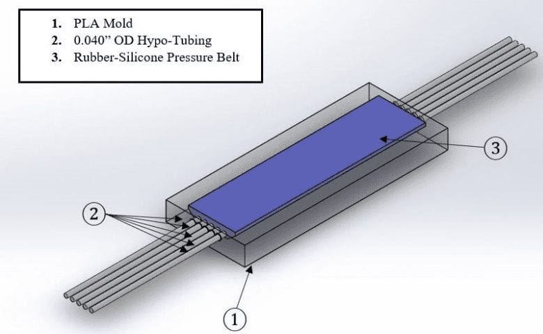
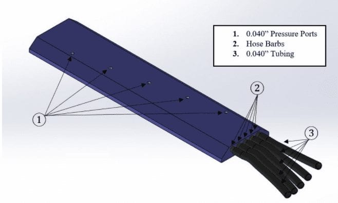
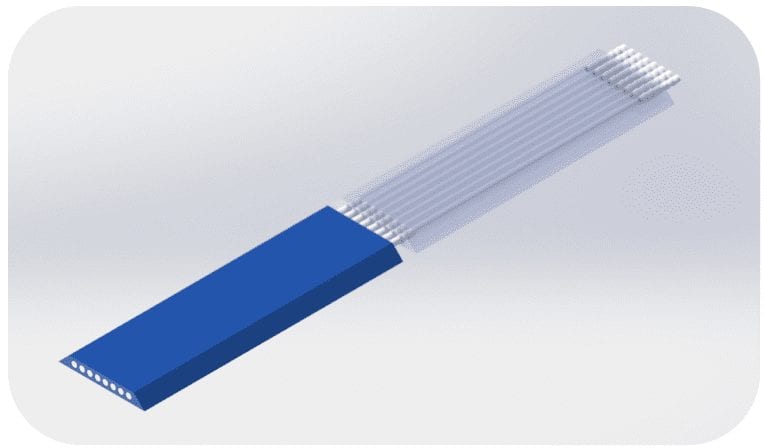
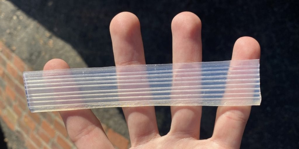
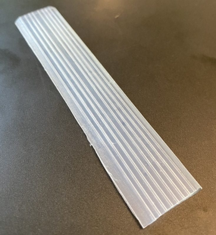
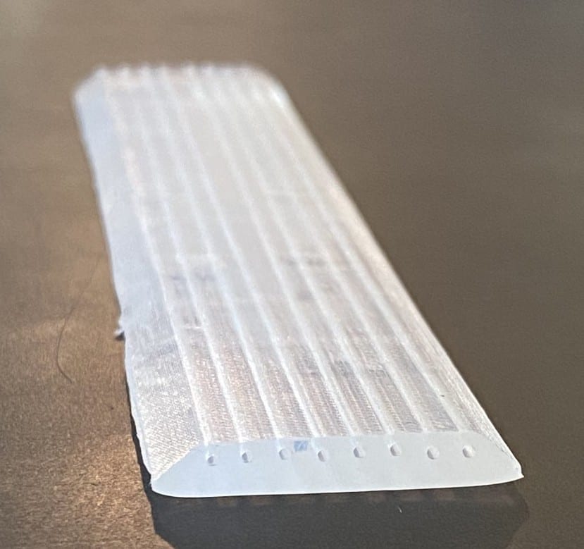
The final design consists of a 3D printed PLA mold with hypotubing inserts. A silicone cast is made from the mold and is later biopsy punched to make the pressure ports.
Specifications
Weight ~ 50 grams
Dimensions – 1.5” X 0.150” X 10.5”
Assembly
The final assembly consists of inserting the couplings between each silicone belt segment to form a larger painting over the front end with more silicone to seal it off, and punching holes on top of the vias with a biopsy punch.
Testing & Design Verification
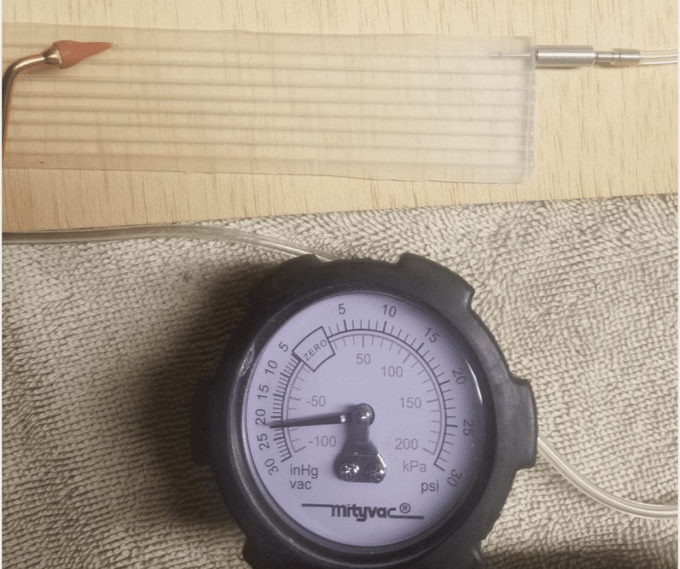
Leak test set up with dental pick and hand pump.
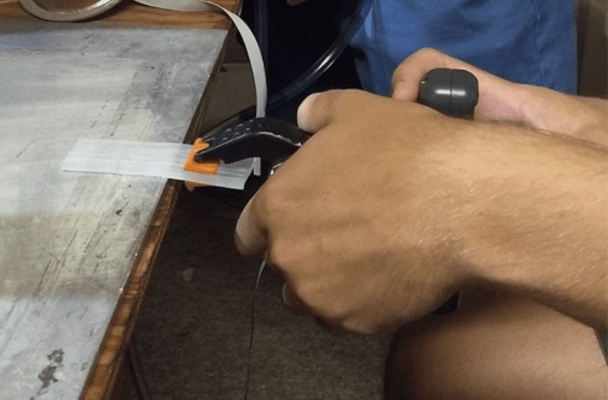
Adhesive test setup.
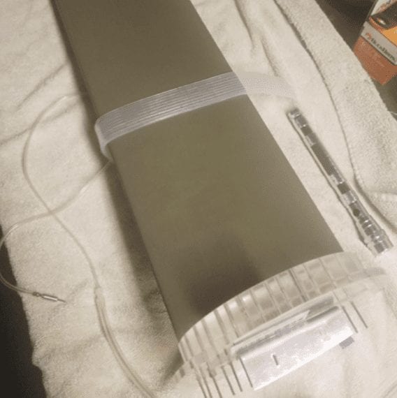
Pressure belt on airfoil for wind tunnel test setup.
Test descriptions
Leak Test – The hand pump is placed in one end of the via and a dental pick is placed on the other. Each via is pressurized to determine if pressure can be maintained without leaks.
Flow Test – The hand pump is used to pump air through each via to check for obstructions.
Adhesive Test – Adhesive is applied to a surface and the belt is placed on top. The belt is pulled parallel to the surface. The force at which the adhesive fails is measured with a fish scale.
Wind Tunnel Test – The pressure belt is applied to an airfoil using the adhesive and is used to capture data in the wind tunnel. This data is compared to known pressure measurements to determine belt accuracy.
Results of Testing
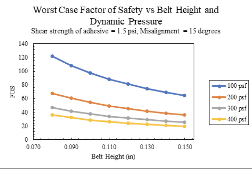
Adhesive test results indicating extremely high factors of safety for the pressure belt.
After multiple iterations, we consistently produced belts which passed the leak and flow tests for all vias. The adhesive test showed that the belt should withstand the shear loads of the a flight test.
Wind Tunnel Test
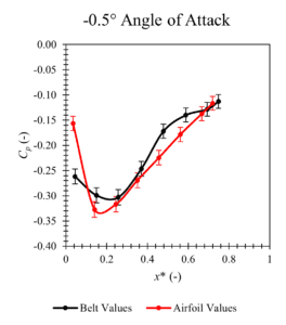
Wind Tunnel Test results. The x-axis is a normalized port position, normalized against the chord length of the NACA 0012 airfoil used. The y-axis is the coefficient of pressure, which is the measured pressure minus the static pressure, all divided by the dynamic pressure.
Manufacturing Process
1. 3D print mold using PLA
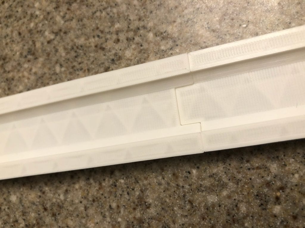
Sections of 3D printed mold attached together with keyed slots.
2. Lightly coat the hypotubing cores with Vaseline for easier removal post curing. Insert hypotubing cores into holes of mold.

3. Pull vacuum on the silicone mixture using the vacuum chamber to eliminate air bubbles for about 7 minutes. Pour silicone mixture into mold and use a heat gun to get rid of any remaining air bubbles. Let the mixture cure for 18 hours.
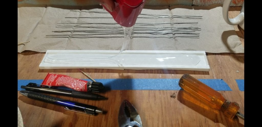
Silicone pouring.
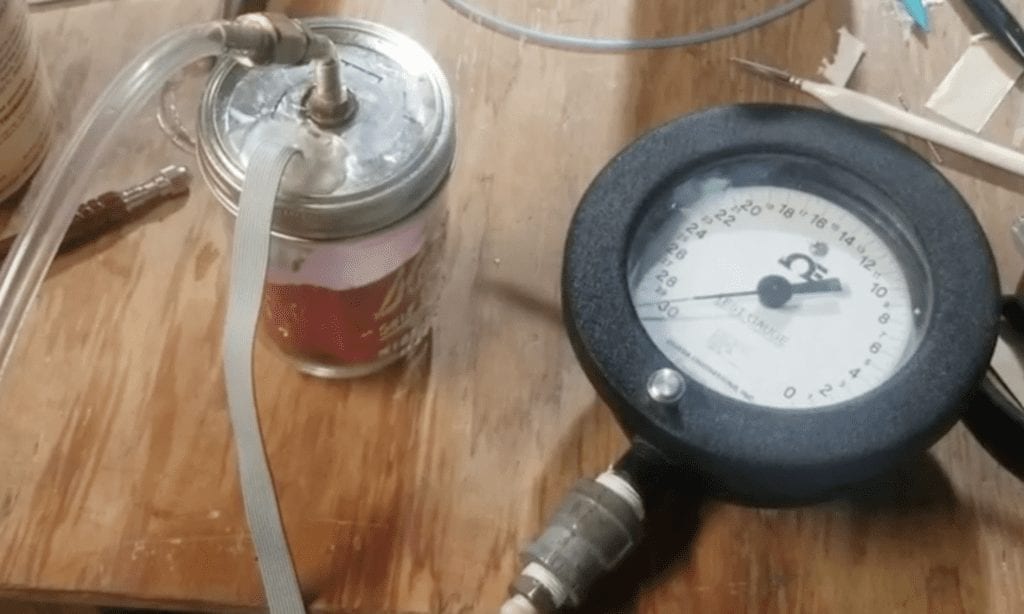
Silicone mixture in pressure chamber.
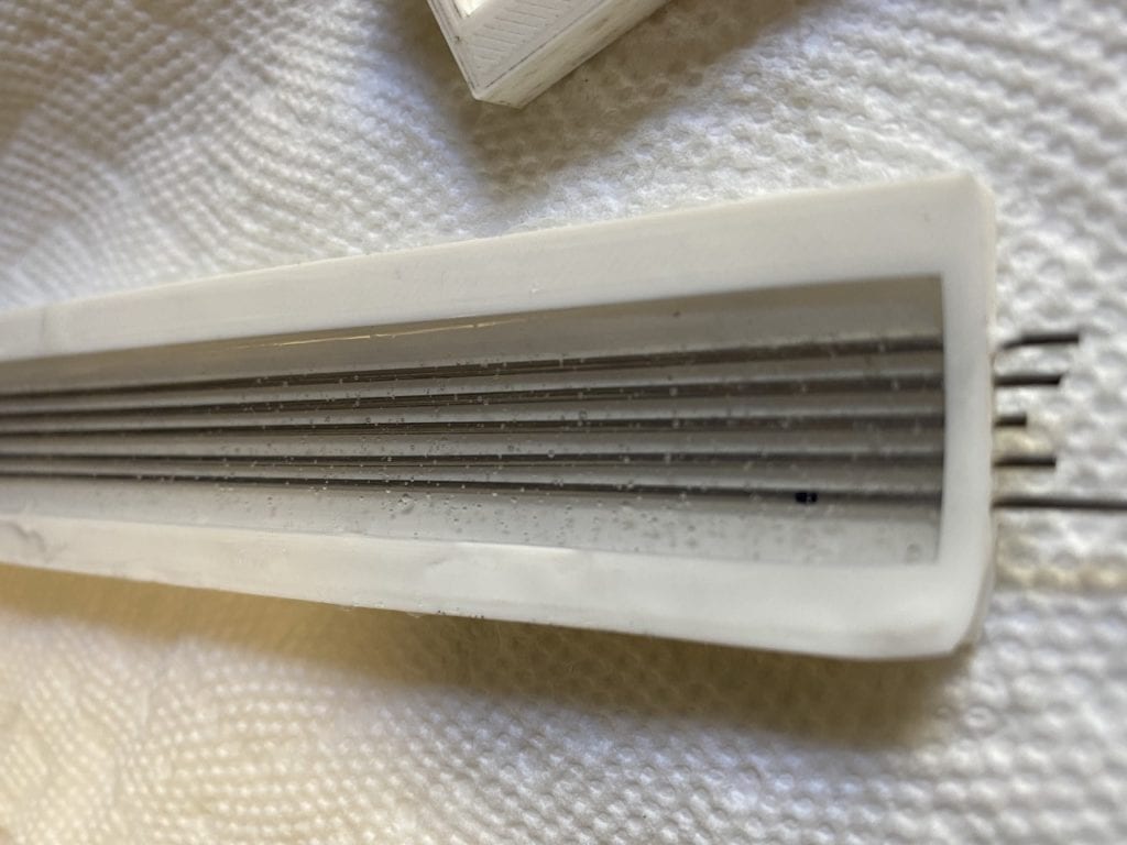
3D printed cast with silicone poured in.
4. Gently remove cores from cured cast. Remove silicone cast from 3D printed mold.
5. Use the biopsy punch to insert the pressure ports on top of the vias based on the desired measurements for the application.
6. Assemble the desired number of silicone belts together using metal tubing connectors that attach each corresponding via. Apply a thin layer of the silicone mixture to the front end of the belt.
7. Connect the last tube in the chain to the BLDS using its corresponding attachments.
8. Apply the adhesive to the bottom of the silicone belt. Place adhesive onto surface in which pressure measurements are going to be taken.
Future Recommendations
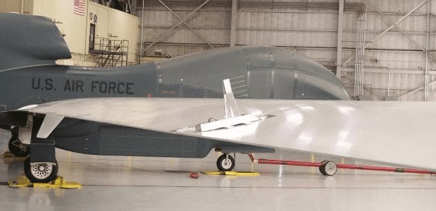
The BLDS being used on a Global Hawk for testing.
Improvements to be made if the pressure belt were to be re-designed:
- Using a silicone mold with a higher Shore hardness to prevent possible damage to the belt during handling/post-processing
- Spread out the vias more by moving them away from the edge of the part to prevent breaching and leaks
- Conduct further testing on the effect of the pressure belt on the boundary layer
