Recliner Worktable

The laptop worktable design project is sponsored by Mr. Harish Bhutani from Monaero Engineering, who sees a lack of market product support for the elderly and individuals with disabilities trying to use their electronics while comfortable in a recliner. Our design team targeted the problem and aim to develop and create a newly designed laptop worktable compatible with most recliners.

Our Team

We are team F22. Each member came from diverse and different backgrounds giving our team an assortment of skills, knowledge, and experience that aided to our team’s final product. 

Matthew Tagupa

Point of Contact / Liaison

I am a transfer student from West Sacramento, California. I was responsible for communication between the team, advisor, and sponsor(s). I was also responsible for making sure that each assignment was done on time and was presented in a professional manner. Aside from my academics I enjoy outdoor activities, including hiking, camping, and archery.

Screenshot_20200806-210324_Gallery

Hector Valle

Team Record Keeper

I am a transfer student from Cuesta Community College, California. Part of my responsibilities were making sure our teams notebook is up to date following team meetings. I was also responsible for verifying members stayed on track with our design progress tasks.

Drake Royce

Scheduler and status reporter

I am a Mechanical Engineering student from the Bay Area. My responsibilities were to prepare our progress status for our sponsor each week, and schedule our goals for the proceeding week.

Jose Chavez

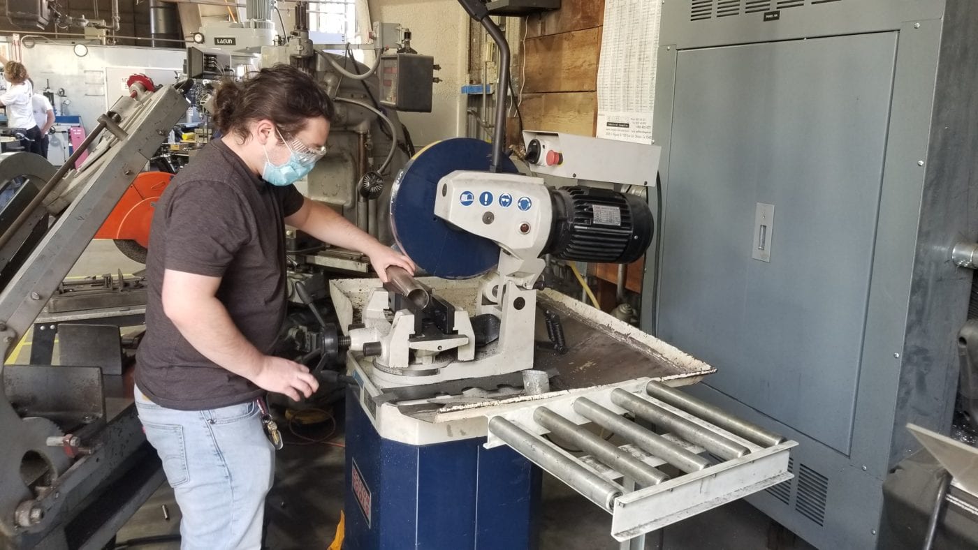
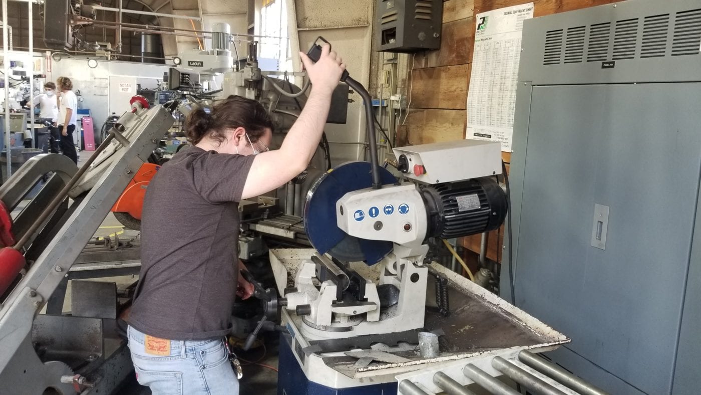
Shop Lead/Safety Inspector

I am a transfer student from Santa Rosa, California. Besides helping my team complete all other tasks and assignments, I was responsible for any shop-related activities, including tech support and safety inspections.

Acknowledgements

We would like to thank Professor Mohammod Noori for all of his support on this project. This project gave our team a great sense of challenge and upheld Cal Poly’s “Learn by Doing” motto. Thank you for all of the great help, Professor.

This project was made possible due to a generous support by Mr Harish Bhutani, President, Monaero Engineering.  We greatly acknowledge his sponsorship of this project, including his generous financial support provided.

We would also like to thank all of the shop techs at the Hangar. Your guidance and patience made working on this project enjoyable and knowledgeable.

We would also like to thank our peers. Your guidance and feedback helped make this project better every step of the way. 

Our Project's Videos

Our Project's Digital Poster

Project Introduction

Mr. Harish Bhutani of Monaero Engineering believed that there would be a growing market of consumers that would be senior citizens. He also saw that due to the COVID-19 pandemic, there was a need for connectivity between these senior citizens and their families. Technology has advanced enough to allow them to connect through their computers and phones, but what could be done to make this social distancing situation easier for seniors? He wanted to create a worktable for seniors. One that would allow them to virtually visit with their family in the comfort of their favorite and most comfortable chair: their recliner. He tasked our team with designing a worktable for recliners that would be modular and relatively lightweight.

Problem Statement

Elderly and people with limited mobility have issues finding a comfortable spot to work due to physical attributes. They need a worktable that is compatible with their recliner while also being easy to use, assemble, and disassemble.

Limits and Expectations

  • Tabletop Dimensions: 30″ x 15″-17″
  • Modular (Can be assembled and disassembled for storage)
  • Lightweight: <15 lbs.
  • Cost to Manufacture: <$100

Initial Designs and Prototypes

Figure 1. Portable Desk
Figure 2. Overbed Table

Existing Patents and Solutions

Our team was familiar with some existing worktables. The two shown above are fairly popular (especially the Overbed Table in Figure 2 which you may have seen in hospitals), but none of the current designs were designed for recliners.

Team Ideation and Challenges

The biggest challenge our team faced was our desire to design the table for any and every recliner. This seemed feasible, but our designs and prototypes were focused on easy use, avoided damage to the users surroundings (especially for recliners that rotate), keeping the table lightweight, and overall keeping the manufacturing costs low. Below are our a few of our initial design ideas.

Figure 3. "Arm Squeezer"

This design would clamp to the bottom and top of the arm rest of any recliner. this way, the table would be off the ground and not damage the floor.

Figure 4. "Bottom Holder"

This design was similar to the one above, but it would be on the ground providing structural support. 

Figure 5. "The Dream Table"

This design utilized an idea of a sliding mechanism to extend the table to utilize support from both arm rests on the recliner.

CAD Models

Figure 6. Version 1
Figure 7. Version 2
Figure 8. Predicted Trolley CAD
Figure 9. Version 3

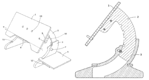
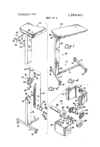
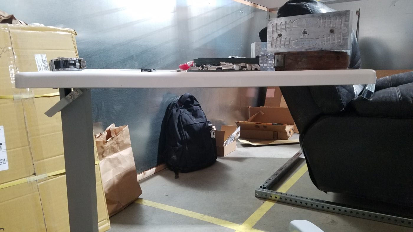
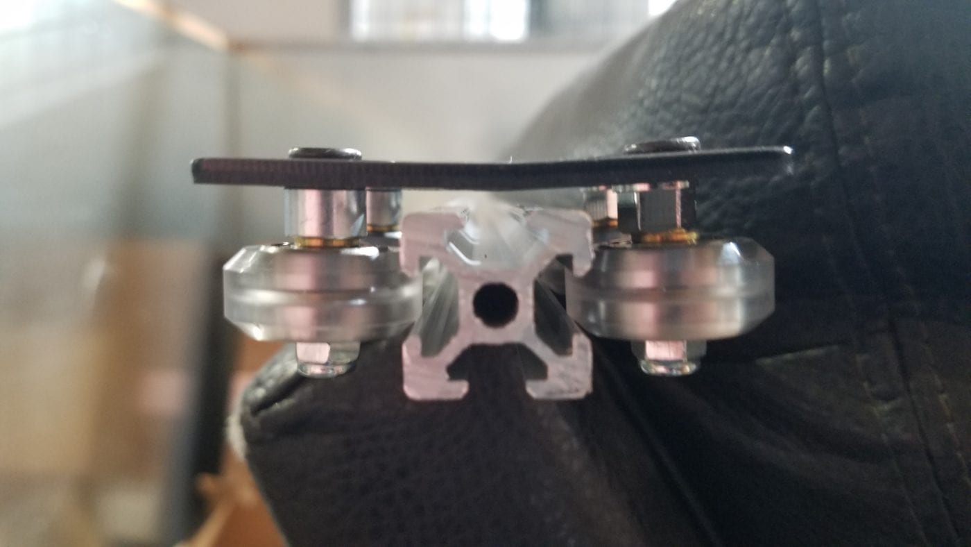
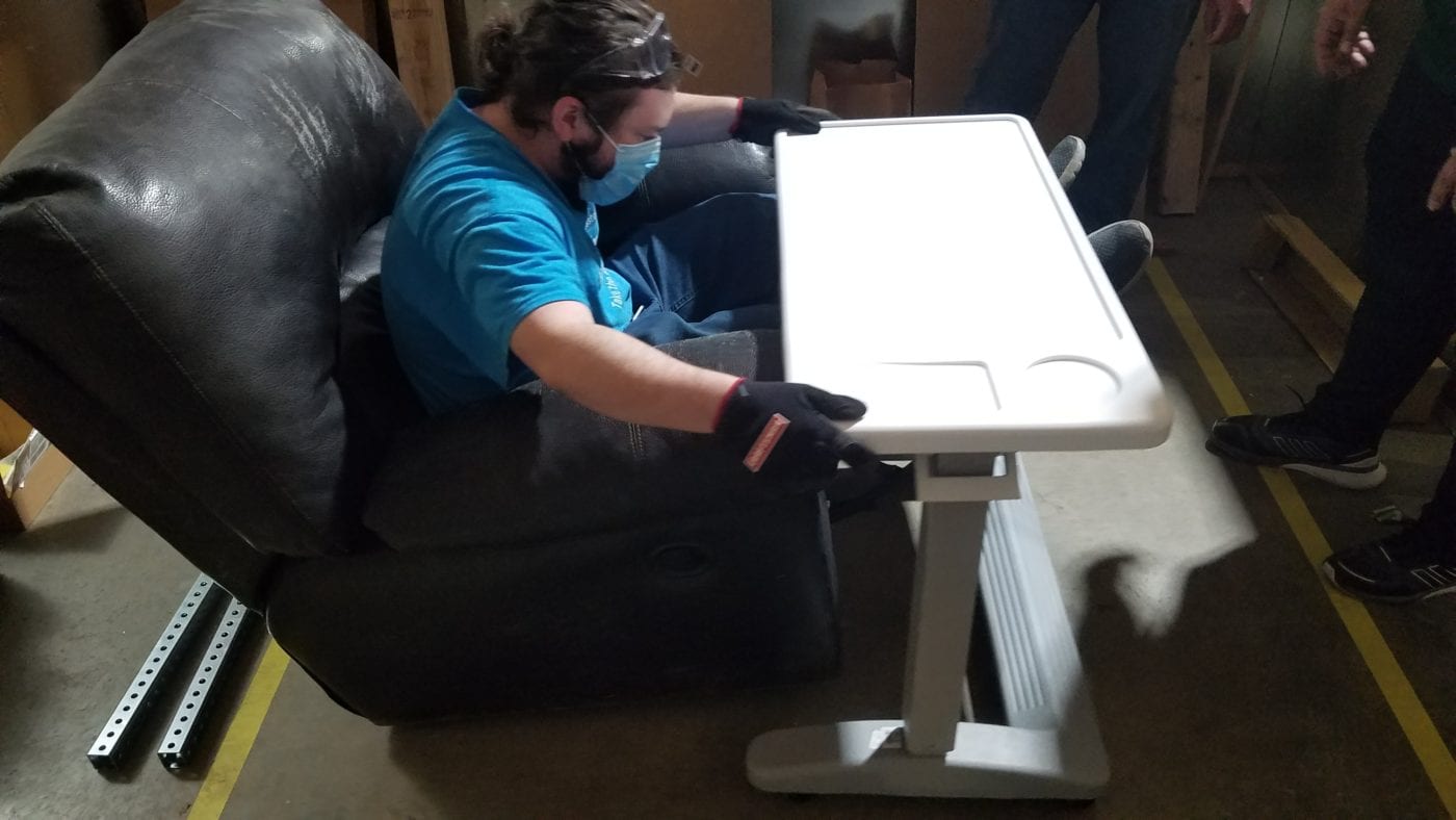
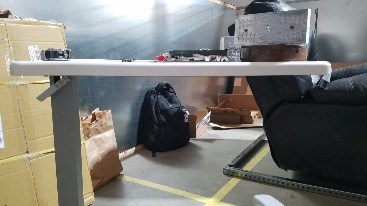
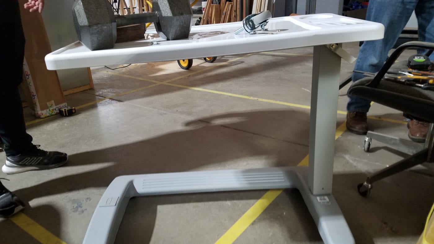
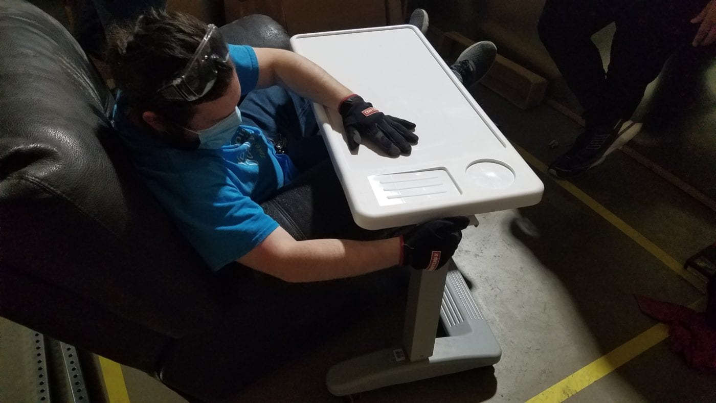
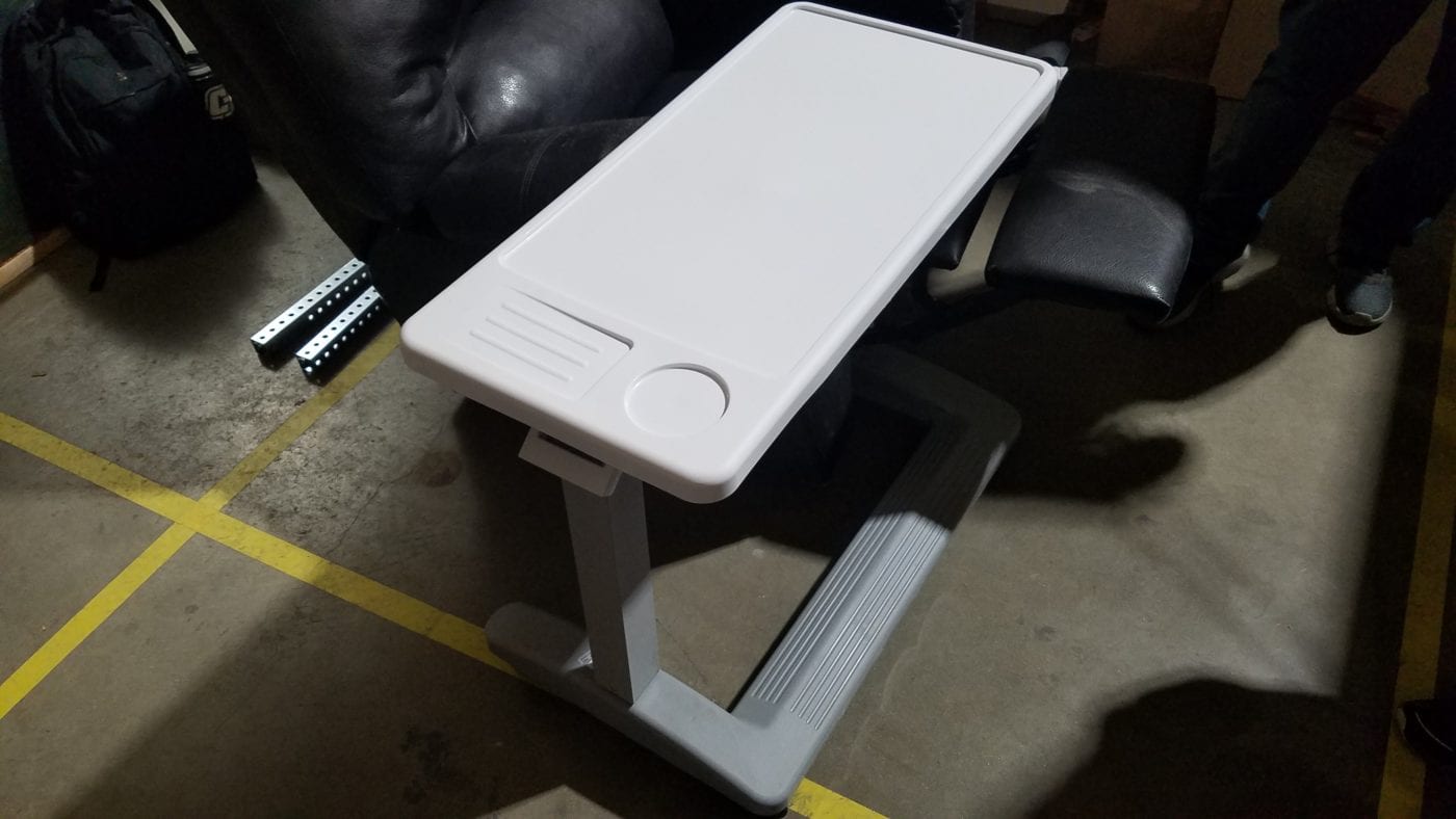
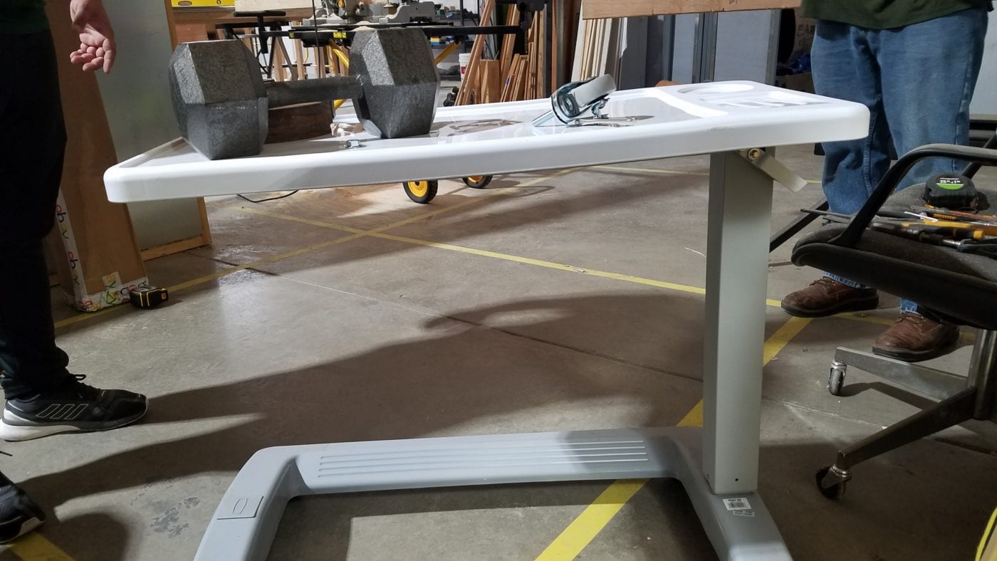
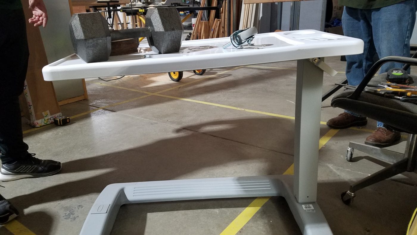
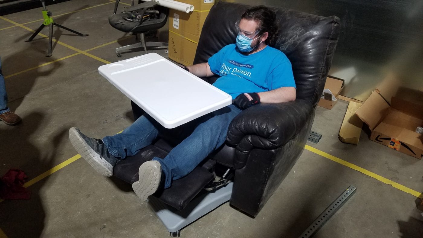
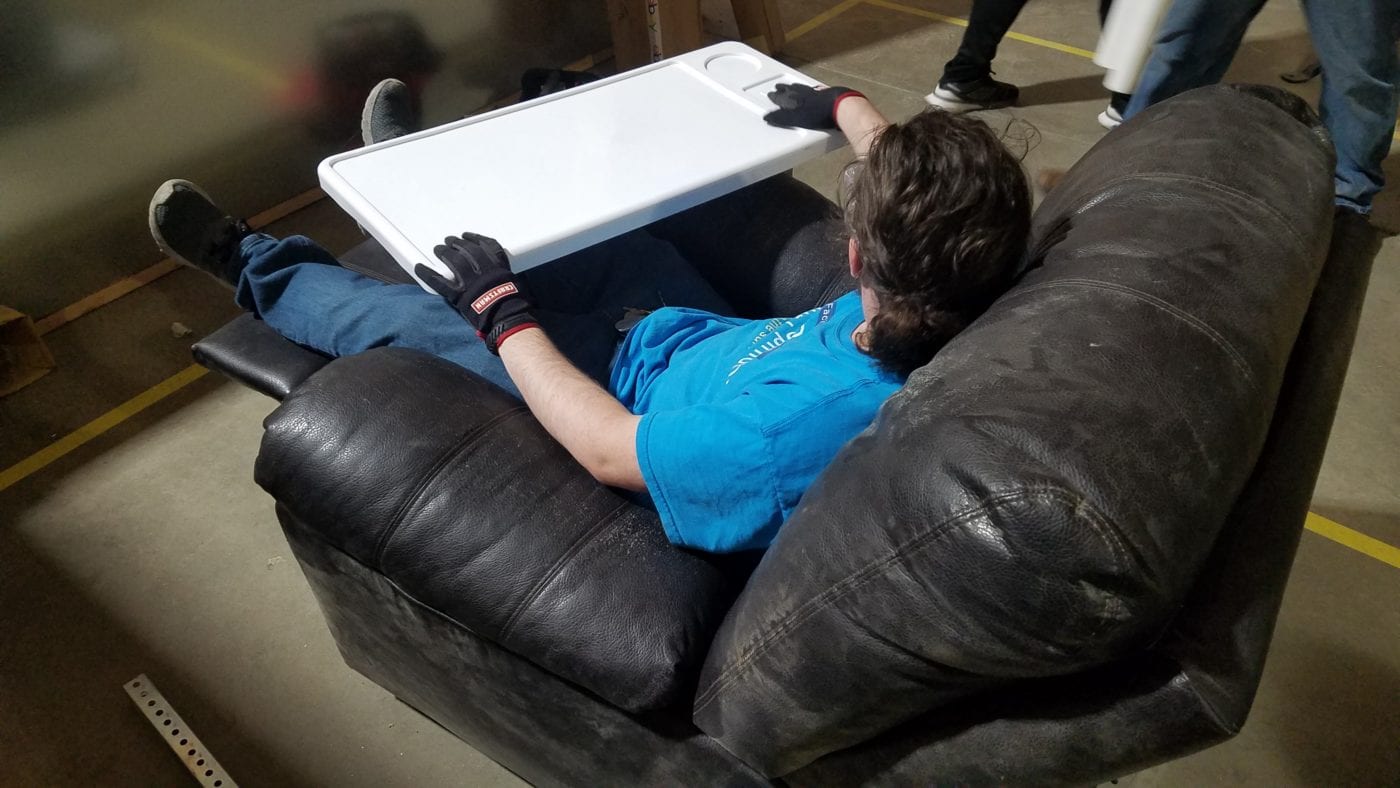
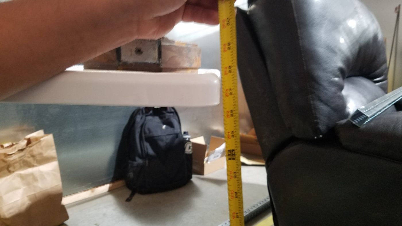
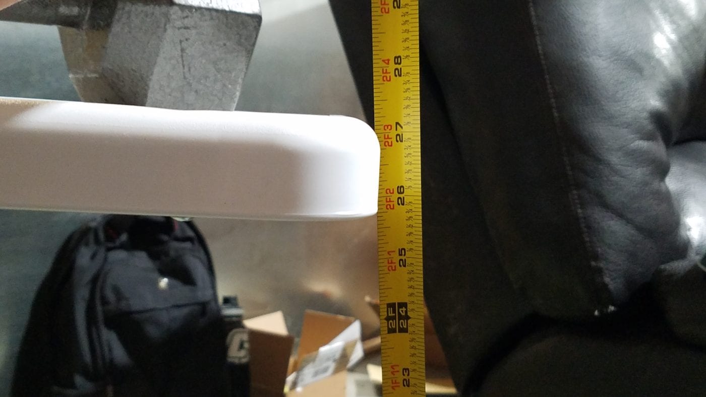
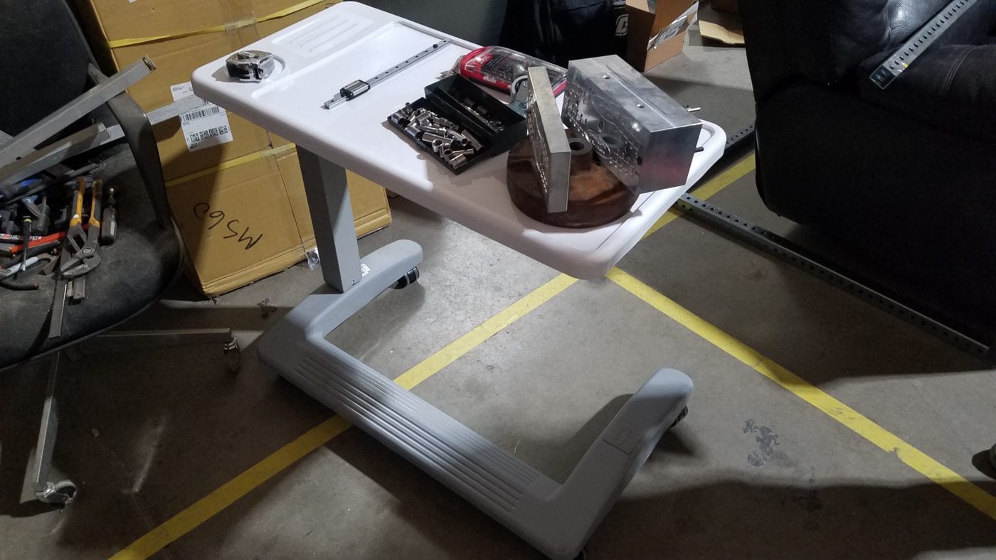
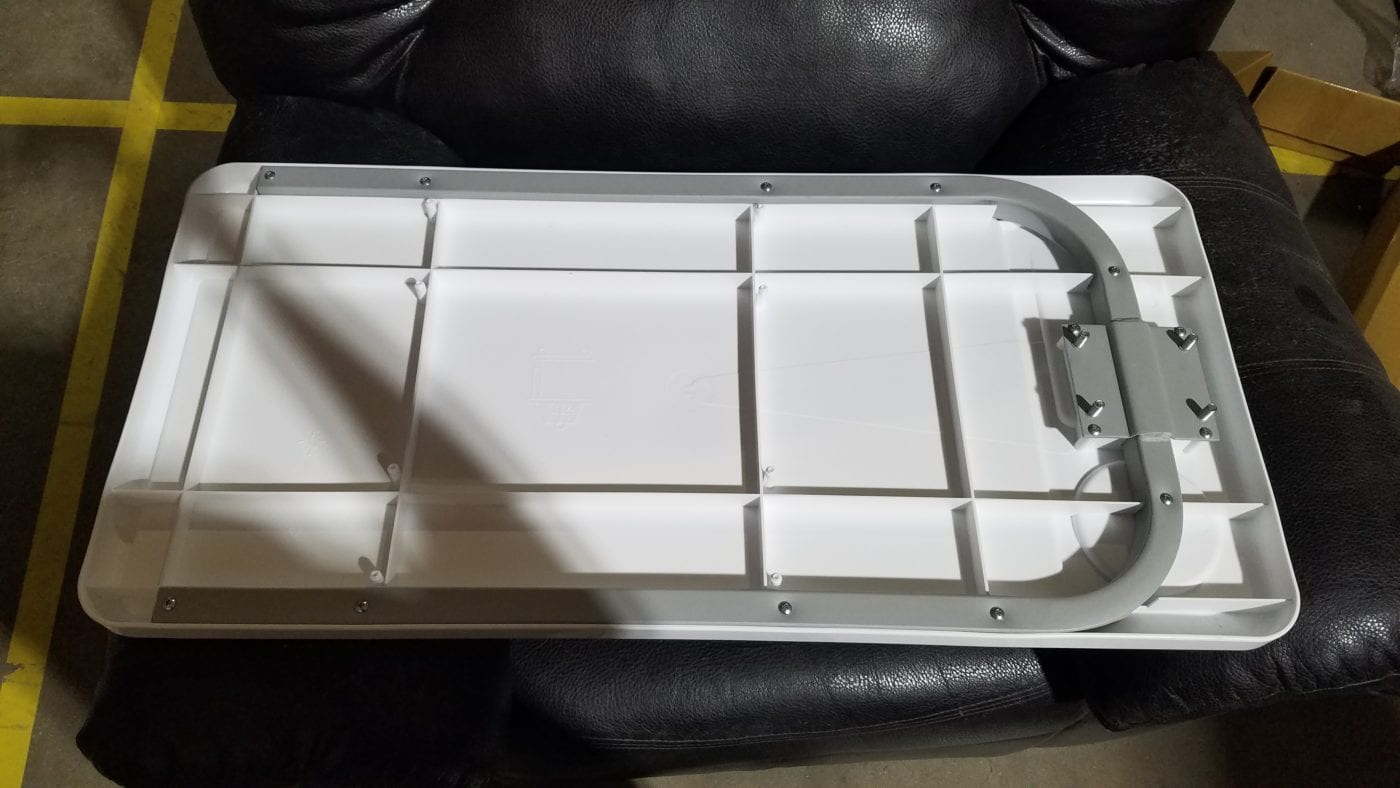
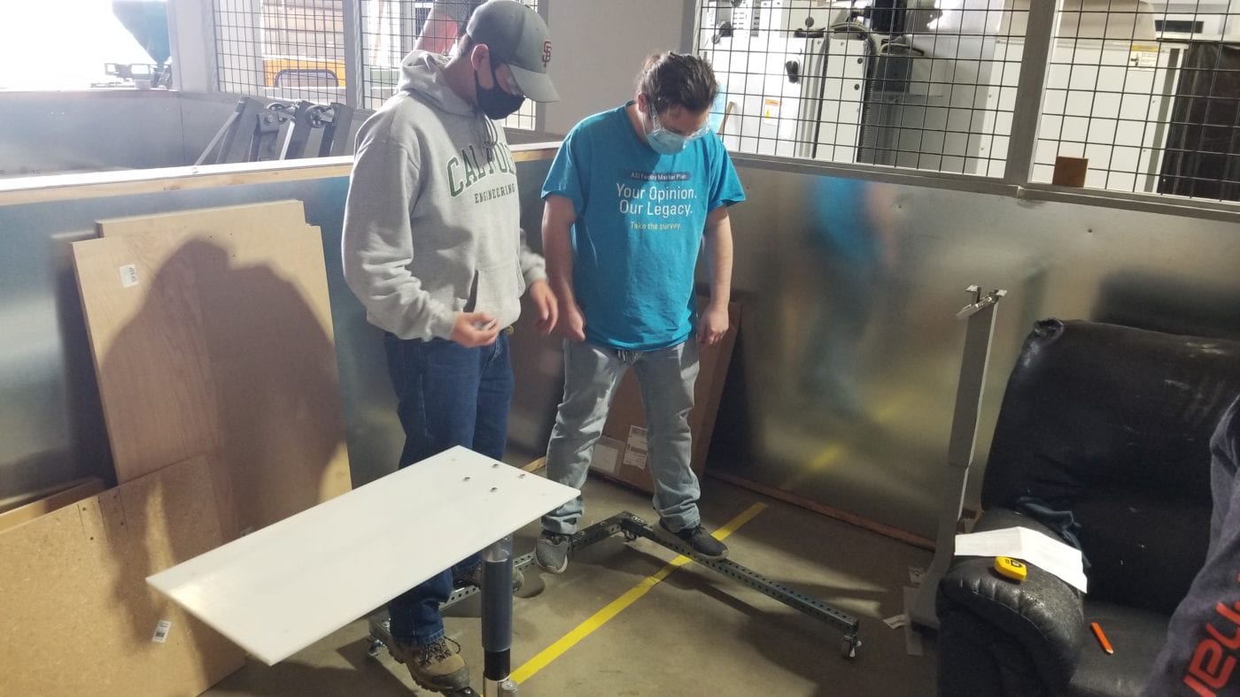
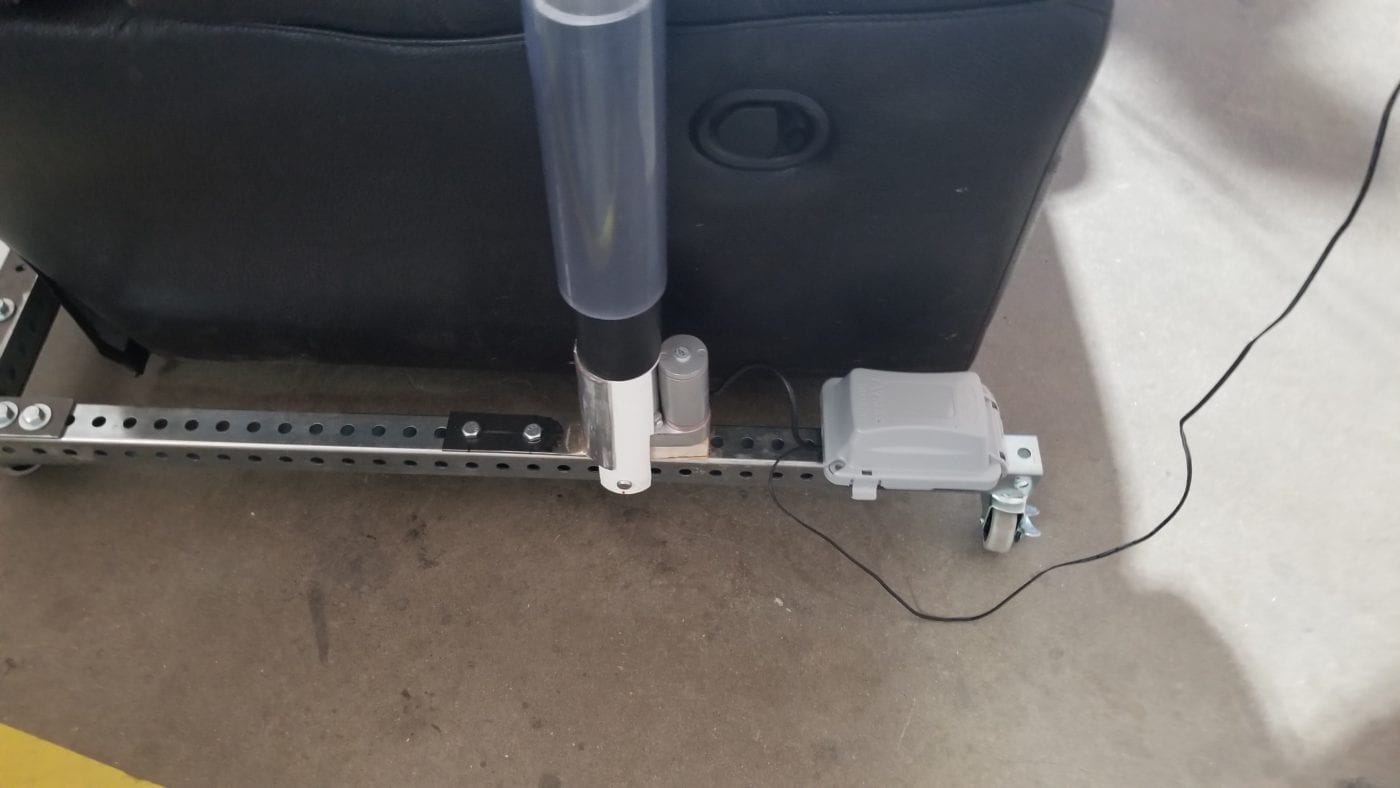
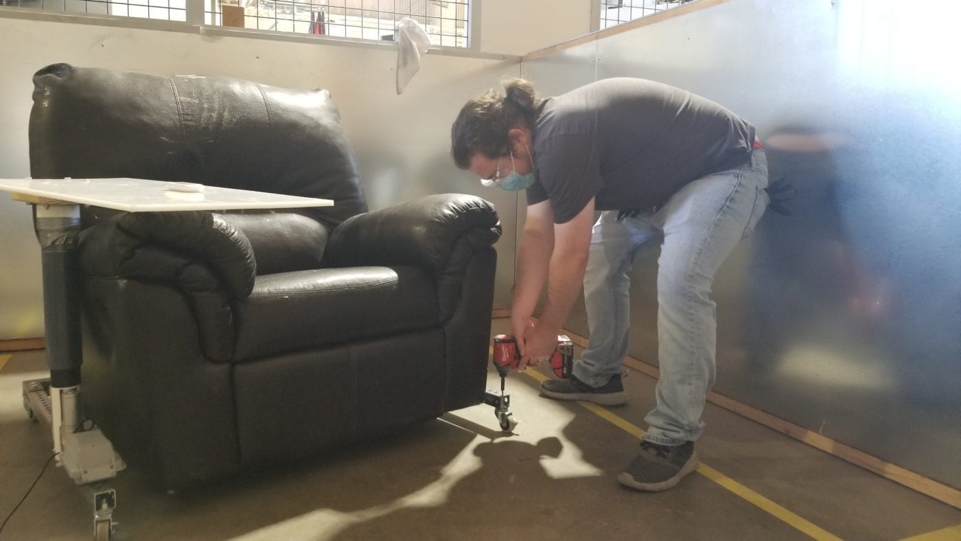
F22 - Recliner Worktable

This project is sponsored by Mr. Harish Bhutani, Dr. Mohammod Noori, and the Cal Poly College of Engineering - Mechanical Engineering Department

Design and Redesign

Version 1

Figure 10. Recliner Worktable Version 1

This was our original proposed CAD model of our solution to the problem that Mr. Bhutani proposed. This model would clamp onto the armrest of the recliner. It included an electrical outlet to allow the user to plug in their laptop without the need to get up out of their recliner. The issues we had from this model were that the tabletop would be heavy if it was made out of wood and there was no support at the top of the armrest making this system rely on the friction between the bottom clamp and the bottom of the armrest.

Version 2

Figure 11. Recliner Worktable Version 2

Version 2 addressed the issues with Version 1. The tabletop would instead be made from High Density Polyethylene (HDPE). This material was lightweight and could be made from recycled polymers, including water bottles. We added axial support by moving the electrical box above the armrest allowing clamping around the armrest to be more stable. 

Version 3

Figure 12. Recliner Worktable Version 3

Both our sponsor and advisor thought that this was an interesting approach, but it didn’t seem as stable after performing some preliminary tests on a prebuilt clamp our group wanted to test. Our team was officially on a time crunch and gathered as many resources for a redesign. The above design was proposed for building. The tabletop would still be made of HDPE as planned before. 

The tabletop would be able to swivel and rotate to move out of the way allowing the user to get in and out of their recliner. The worktable would now use a steel base heavy enough to counter any weight applied to the table while it is swiveled outward. Beneath the square steel punched rail would be caster wheels to make moving the table across multiple surfaces of different roughness relatively easy. The table would swivel with an outer polyvinyl chloride (PVC) pipe around an inner PVC pipe. Inside the inner PVC pipe would be a housed linear actuator allowing the user to raise and lower the table with ease. The slide rail would be cut to a shorter length and slide the table closer and further away from the user.

Manufacturing Pictures

Manufacturing Processes

Figure 13. Final Design and Assembly

Specifications
Weight: 20 lb
Dimensions: 36″ x 40″ x 25″-34″

Stock Components

  • Tabletop
  • Square Punched Tube
  • Linear Actuator
  • Linear Actuator Controller
  • HDPE
  • T-Frame Trolley
  •  Caster Wheels

Custom/Altered Components

  •  L-Brackets
  •  C-Channel Beam
  • Wood Block Connecting Tabletop to 2-1/2″ PVC Plug
  • 2-1/2″ PVC Slip Cap
  • 2″ Wood Plug
  •  2-1/2″ PVC Pipe
  • 2″ PVC Pipe

Verification Tests
(Still Editing)

Figure 14. Caster Wheel/Punched Tube Test

With a combined load of 300+ lbs we were sure this table was going to withstand almost anything.

Figure 15. Tabletop Deflection Test Results

The linear correlation of weight applied to deflection of the tabletop assembly.

Additional testing performed

Caster Wheel/Punched Tube Test (Figure 14)- Tested the structural integrity of the base and the caster wheels. These components easily supported more weight than expected. 

Linear Actruator Strength Test- Tested the structural integrity of the Linear Actuator. It held 70 lbs of axial force as expected.

Slider Rail Test- Tested the structural integrity of the Slider Rail. This component failed as it allowed a natural deflection of the tabletop free end.

Tabletop Deflection (Figure 15)- Tested the deflection of the tabletop while it was attached to the rest of the assembly.

Final Design

Figure 16. Final Design

This was our final design. We knew that there were some altercations we needed to add to Version 3, especially after the verification tests we performed. We ditched the T-Frame rail and trolley because it was not stable enough to hold the tabletop weight. We also needed a support for the cantilever of the tabletop, so we added a C-Channel rail underneath the length of the tabletop to oppose deflections at the end of the worktable. 

We seemed to be having some issues with the outer PVC pipe and tabletop attachment not retracting with the linear actuator. Fixing this, we added a plug connection that would fit into the 2″ PVC and be attached to the 2.5″ PVC plug. Also, the table had a natural deflection due to the tolerance between the outer diameter of the 2″ PVC pipe and the 2.5″ PVC pipe. To minimalize this, we filled in the space with Black Adhesive Shelf/Drawer Liner. The linear actuator still had that clevis pin nub at the bottom of it. That nub didn’t fit into the punched holes of the base, so we designed a block that would have a hole at the bottom of it, raising the linear actuator 3/4″. We noticed some stability with the vertical support assembly, so we attached an extra steel support that would screw into the base assembly. 

Final Thoughts

Although This project was functional, there are a few suggestions we have for other teams that work on this project:

  • Communicate with some materials engineers. They may have great suggestions when it comes to the material you use for the tabletop and possibly a cover for the bottom.
  • Look at projects already on the market. You can gain more insight from those projects by seeing how they built their tables.
  • Keep an eye on tolerances. Ultimately most of the deflection of our tabletop came from loose tolerancing between the PVC pipes.

Have a Question About this Senior Project?

Send an email to pschuste@calpoly.edu to be connected with the project team. Please include the title of the senior project you’re inquiring about in the subject line.

Interested in Sponsoring a Mechanical Engineering Senior Project?

Visit our Sponsorship Page to learn more!

Check Out More Projects!

Visit our ME Senior Projects Page to view the latest Mechanical Engineering senior projects from the class of 2021!

Share

Share on facebook
Share on twitter
Share on linkedin