Our Team

Luis Corrales
Testing Lead
Hi I’m Luis, and I was responsible for testing our composite panel designs as well as pioneering new testing procedures to fit our desired application. I also specialized in analyzing our data.

Asa Cusick
Project Manager
Hi I’m Asa. I was in charge of the project’s timeline and progress. I assisted in panel manufacturing and testing, and I guided the report documentation for the project.

Joelle Hylton
Manufacturing Lead
Hey, I’m Joelle. I was responsible for a majority of the manufacturing of the composite panels and determining the required testing methods for each panel. I have also created all of the visuals for this project.

Wyatt Pauley
Design Lead
Hi I’m Wyatt, and I was responsible for the overall design process of the panels for the specific application of our project. Additionally, I helped manufacture all of the panels.
Acknowledgements
Special thanks to our advisor, Dr. Eltahry Elghandour, and our project sponsor, Charlie Guitierrez. Additionally, this project would not be possible without the help of the CP Connect and the R-IDC grant foundations.
Project Videos
The Details

This project is sponsored by Charlie Gutierrez of OnYerFeet, in conjunction with the CP Connect and R-IDC Grant Foundations.
Project Overview
composite panelling for a wheelchair
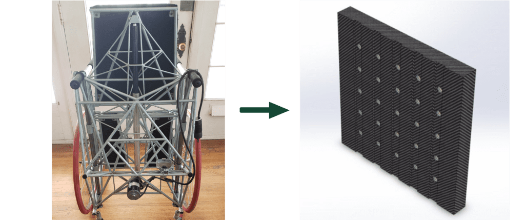
Our design challenge was to determine the best possible core structure and material for use on a composite wheelchair that would allow users to sit, stand, and walk again. This project is intensive in terms of manufacturing and the iterative design process, with the end goal of determining the most cost effective and strongest core combination.
Existing Design
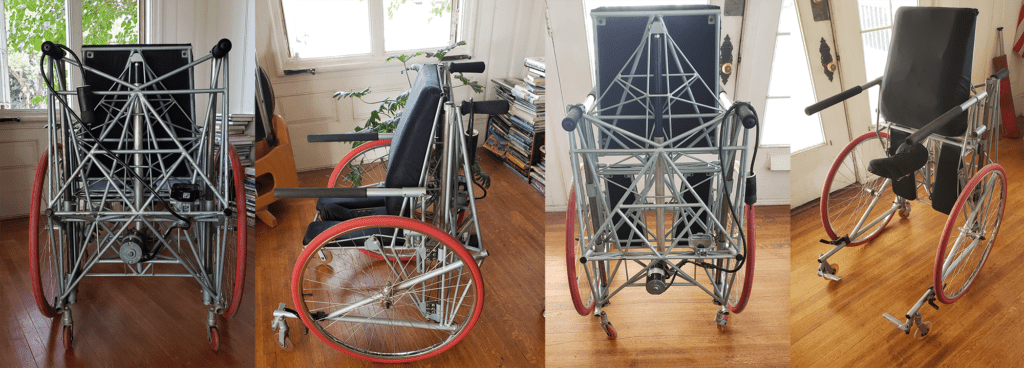
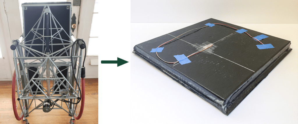
The current design provided by our sponsor is heavy, bulky, and difficult to manufacture. It is currently made of 3 separate truss structures built from Chromoly steel, and a large actuator to raise the chair up and down. This current prototype cannot be lifted by one person alone, let alone someone who would need to use a wheelchair on a daily basis.
Possible Layups
ADAPTIVE SOLUTIONS
During the brainstorming process, the team hypothesized that there were many solutions to the problem at hand. In doing so, we designed, fabricated, and tested seven different panel ideas.
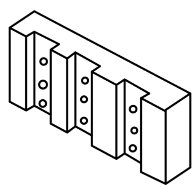
Our sponsor has a goal in mind of creating a successful wheelchair, one that is able to adapt to any situation. Many of the patients who have utilized Charlie’s designs had an additional disability which the wheelchair did not accommodate for. Now that Charlie has decided to reduce the three truss structures in the chassis, he suggested that the new chassis would be adaptable for all disabilities. The team decided after narrowing down the options that this panel to the left would be the best path forward in terms of ease of manufacturing and adaptability for individual users. The panel could even have metal inserts to support the holes required to make the panel adjustable for each user.
We created a list of criteria that our panel needed to satisfy, and from there listed various iterative solutions to the original design. In terms of satisfying the original request to make the chassis lighter, the team agreed that composites would be the most successful path to keep the chassis rigid while maintaining structural integrity. In regards to accessibility, Charlie suggested a pegboard solution that would allow users to attach whatever medical devices needed to support themselves while using the Dynawalk Wheelchair.
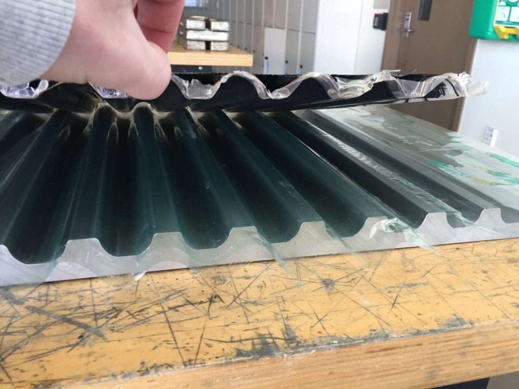
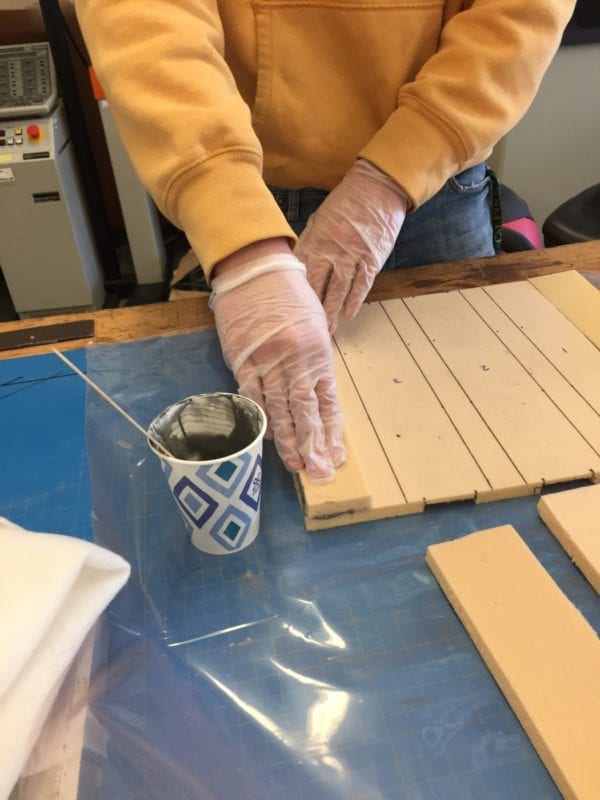
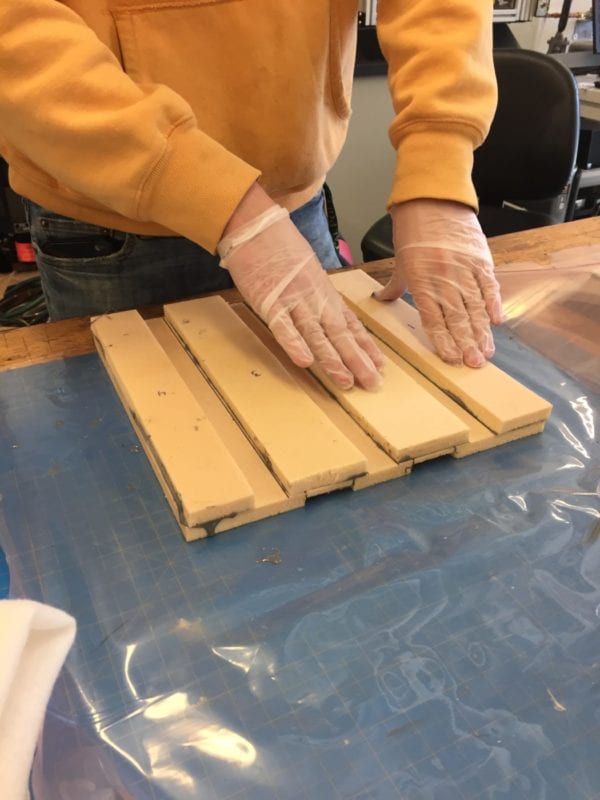
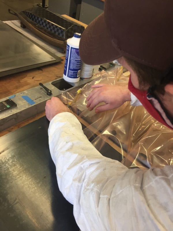
General Layup Technique
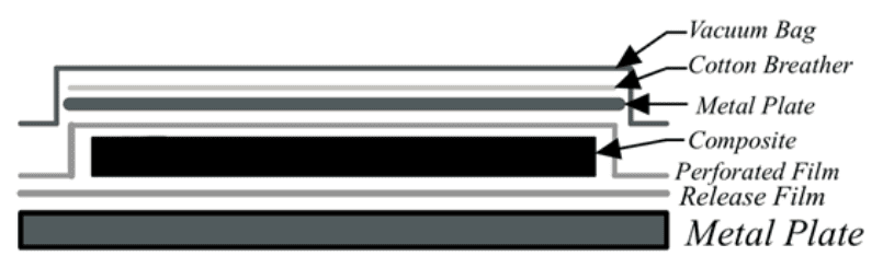
We needed to familiarize ourselves with the general method of composite layups, and by doing so, also created one of our first testable panels. In the image above, a general method for a flat panel layup is depicted. There are many layers that make up the composite panel layup, but the most important addition to the setup are the release films. These films allow for a nonstick surface that will leave a shiny, smooth surface finish on the final panel.
Composite Panel Iterations
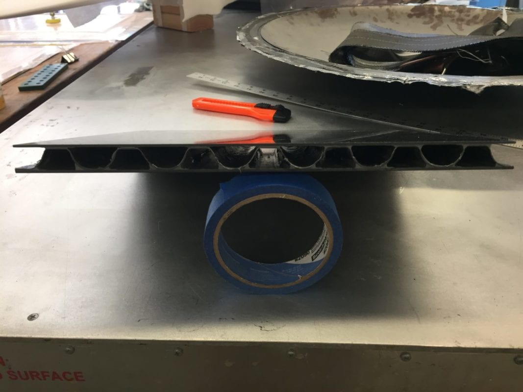
CORRUGATED CARBON FIBER CORE
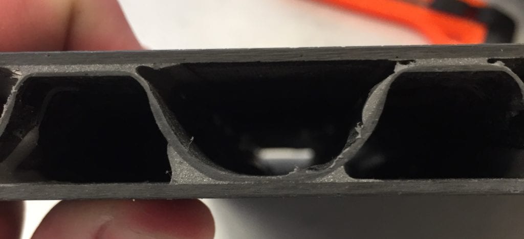
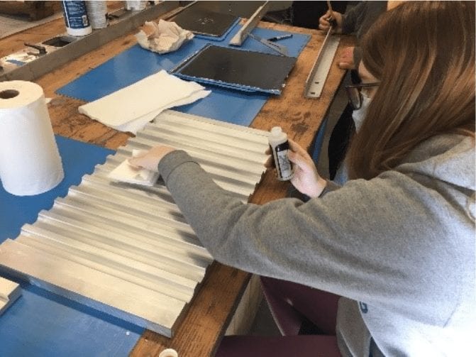
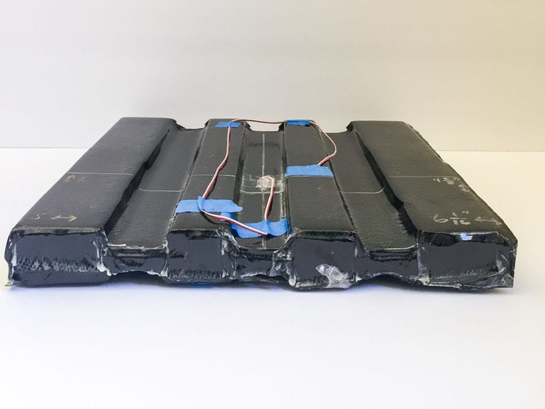
Once we had the hang of the panel layup for the flat panel, we moved on to our first iteration: the corrugated composite core. Pictured above, you can see the cross-section with the corrugated core as well as the structural adhesive holding the two flat panels to the corrugated panel. To make this shape, the mold to the right was used. We were able to load in the sheet of carbon fiber and press it into the mold cavities to create our desired shape. This panel in particular did not meet our demands for simplicity of manufacturing for many reasons. The first of these being the issue of prepping the mold; in order to create a nonstick surface, we needed to sand the surface, clean the mold, and wax it three times. After this first layup, there were two additional layups required to finish this panel.
There are two other flat panels required for this build, which then need to adhere with structural adhesive. While this design is potentially aesthetically pleasing, it has little practicality for our desired application and ease of manufacturability.
CHANNELED FOAM CORES


Two iterations of our design involved foam; two separate foams with two different densities. The image on the left is our first design incorporating a foam core, the thin foam channeled panel. This channeled design was beneficial at first, but upon further manufacturing, this design seemed to be one of the more challenging layups similar to the corrugated core previously. The thin foam panel required similar structural adhesive but was very flimsy due to the shape of the design. This was not a successful design. The image on the right shows our second iteration using a foam core. This design utilized a thicker, more dense foam and was a successful layup. This design did require two layups to complete, but both were successful and yielded a pristine panel. This is also our first design hypothesized.
FLAT PANELS (HONEYCOMB CORES)

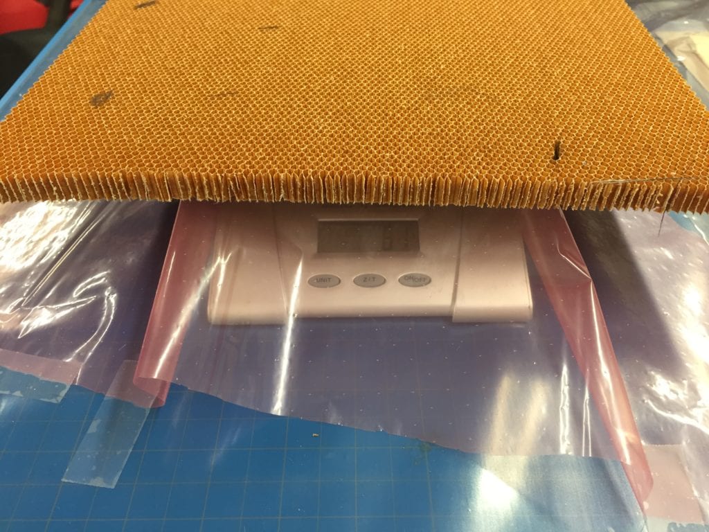
This is the final panel of a fiberglass honeycomb core. It is similar in style to the thin paper honeycomb on the right, but it is fully wrapped in carbon fiber in this image. Unlike the thin honeycomb, this fiberglass core is much stronger and has a higher resistance to bending loads. We also aligned the weave for maximum panel strength.
This is the core only of the thin, paper honeycomb panel. As you can see, each row has a honeycomb shape and is made of paper glued together. There is a specific direction that gives the honeycomb a strength to resist bending and shearing. Our weave pattern mirrored this direction to maximize our panel’s strength. You can get a closer look at the honeycomb core in our slides below.
alternative/cheaper materials

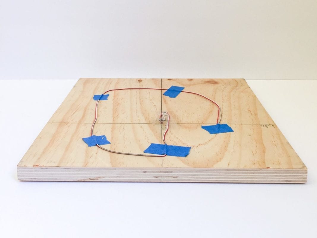
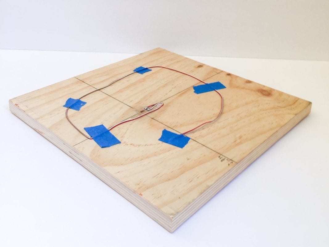
Our sponsor was also interested in creating a more cost-effective design, as that was the main goal of this project. In order to find other materials, we brainstormed using new cores that were sustainable, reclaimed composite fibers, and even explored alternatives to epoxy resin. Charlie was most drawn to using a special type of plywood: Baltic Birch. Per his request, we tested the panel by itself (left) and also wrapped a panel in carbon fiber (right), and tested both.
thin FOAM PANEL

Dr. Elghandour also suggested the design to the left: a double core panel separated by a layer of carbon fiber. This design was a new iteration of a single flat panel and a deviation from the channeled foam core panels. This panel performed quite well in our testing and is also very light. The results for this panel are the most promising thus far. In terms of manufacturability, this panel design was the simplest of all the foam layups because it could be done in a single run and required fewer layers. In comparison to the channeled foam designs, which took two layups and structural adhesive, this design required no additional manufacturing and used epoxy and carbon fiber as the adhesion between layers. This design uses the same foam as the thin foam panel but there are no channels in this design.
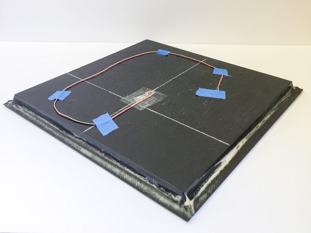
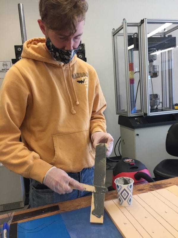
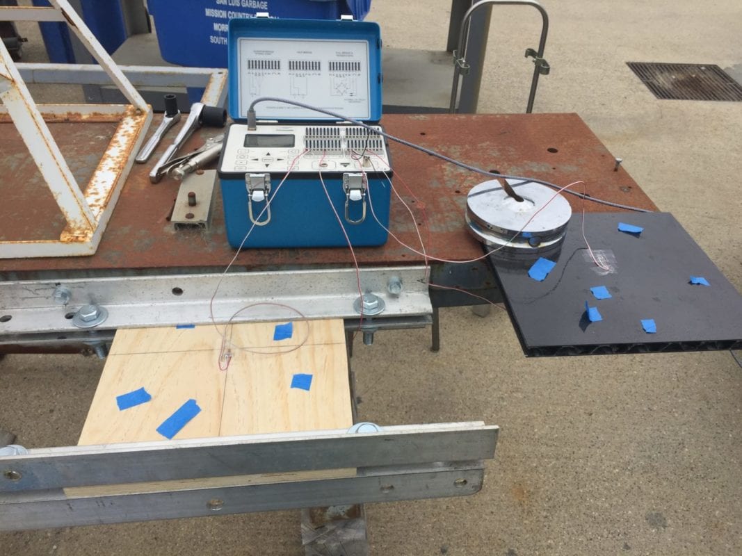
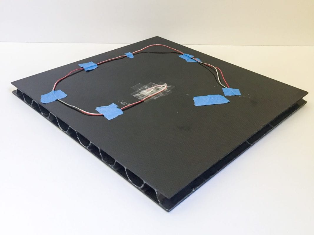
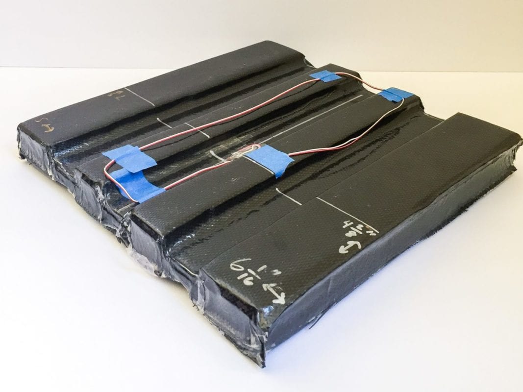
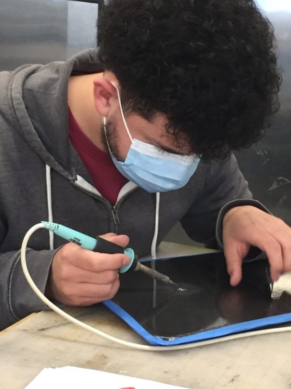
Pioneering a New Test
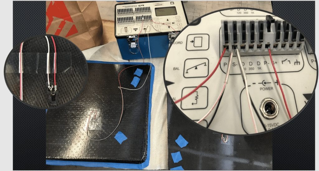
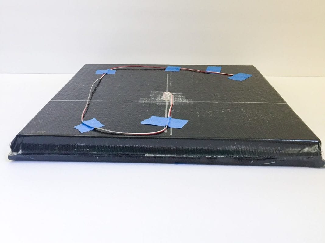
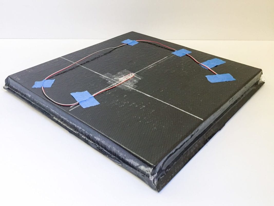
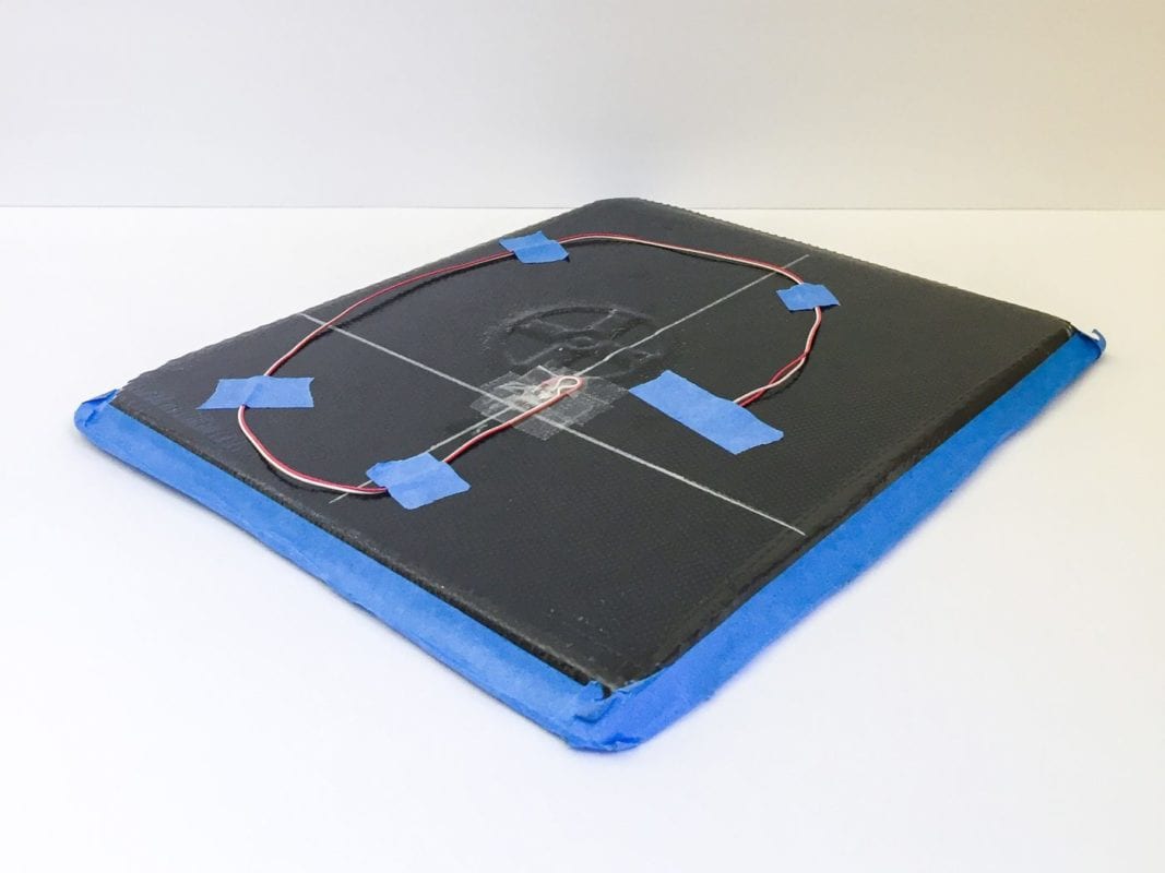
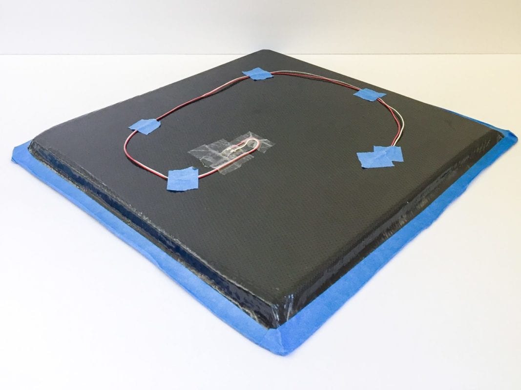
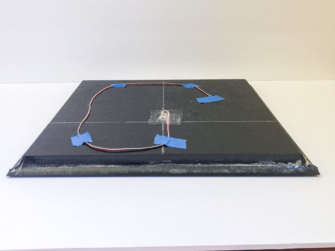
Currently, there are no standard testing methods for the application of bending loads in the industry. We brainstormed and fabricated a way to accurately predict how our panels would react to a cantilever bending loads. This required the creation of a new fixture to secure the panel while we could apply a load as a cantilever and test the panels’ endurances simultaneously. Doing so required us to solder strain gauges on to the top and bottom of each panel to measure the strain through the fibers.


After the completion of the panels, application of the strain gauges, and manufacturing of the cantilever testing fixtures, the cantilever testing can be performed on the panels. The team began with the paper honeycomb panel. The panel was set up in the cantilever fixturing with the strain gauge perpendicular to the fixturing clamp pieces. The fixturing clamp pieces were measured parallel to ensure the weight was being applied in the direction of the strain gauge. We tested each panel 5 times and recorded the strain on each panel at each weight interval. By doing so, we were able to graph the linear deformation rate for each of the panels to determine Young’s Modulus.
Bending Analysis
Following testing and recording the data, we compiled all of our points in MATLAB to compare the strain and deflection of each panel.
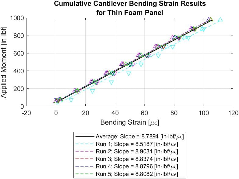
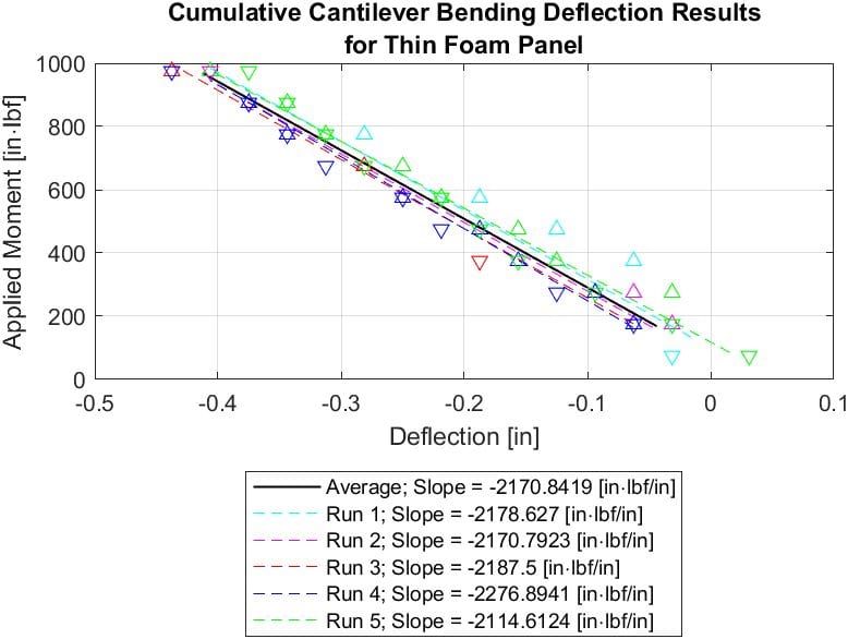
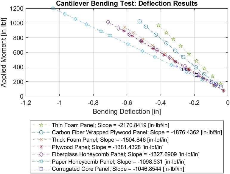
The data above is for all the runs for the thin foam panel. Each run and its respective slope are shown for both the strain and the deflection. The data shows the general trend for each panel; the more force applied to the end of the panel, the higher the strain and deflection throughout the panel. This method of collection and comparison was completed for each of the panels to compare and find the average for each panel over its five runs.
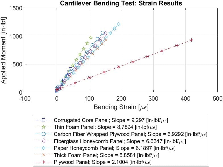
Each of the panels’ averages were compiled onto a single graph so that we could compare the overall trend for each panel with respect to the strain (left) and deflection (right) in order to find the best selection. For the strain comparison, the corrugated panel has the highest slope, leading us to believe that this panel could be the best choice, but the thin foam was much better in the case of deflection.
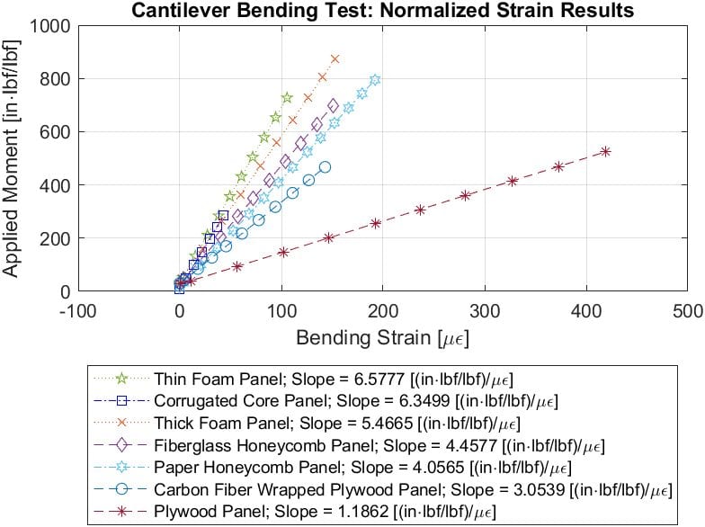
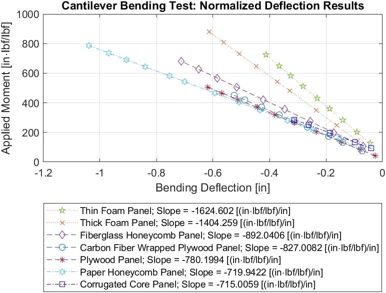
To fully compare the data, it was necessary to compare them on an equal level; in other words, we needed to see how each panel would compare to each other in relation to its stiffness and weight. To compare, we needed to normalize the data, meaning that we took our existing data points and divided each panel by its weight; this value can be referred to as its specific stiffness. Above is our final comparison graph showing the normalized strain (left) and our normalized deflection (right).
Final Design Choice
The thin foam panel was chosen as the best design to move forward with due to the differences in the normalized strain and deflection graphs in comparison to the other choices for panels. It is also our easiest to manufacture, needing only one layup to create this design. Overall, this panel is light, effective, and easy to manufacture making it the best option.
Recommendations
for manufacturing
In regards to manufacturing, the final panel selection was possibly the simplest to manufacture of all the iterations completed. For future manufacturing, we recommend completing the panel in a single layup to provide the best adhesion for the entirety of the panel. In terms of alternate materials, it is worth looking into using different types of foam, possibly cheaper materials than we selected. We don’t fully know how the density of the foam or the thickness affects the specific stiffness of the panel, but we suggest substituting a foam that is similar in properties to the thin foam we selected.
FOR WHEELCHAIR DESIGN
For the wheelchair design, it is very important that more research be done on the interface between the composite panel and the existing frame. During the design process, we researched a few different solutions but did not go further with any of our designs due to time constraints. We also suggest that it might be possible to create the entire frame out of composites, but the shape of the panel might need to be adjusted to accommodate this design direction.
Future Plans
In the future, we hope that our design can help millions of wheelchair users around the world find a way to rehabilitate successfully and safely. This data will be delivered to our project sponsor, Charlie, who will design and fabricate the interface between the original chassis and our new panel design to create a lighter frame.