Our Team
We are a team of four 4th year mechanical engineering students. The possibility of our design flying to the moon on astronauts’ space suits for the Artemis program brought us together and helped keep our teamwork fun and effective.

Andres Elzaurdia
Lead & Analysis
Led the team throughout design, manufacturing, and testing. Performed finite element analysis in the detailed design phase. Created the design verification plan and aided with testing.

Cole Stanton
modeling & Manufacturing
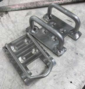
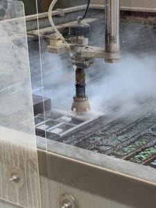
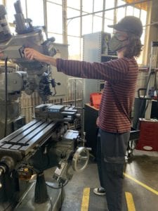
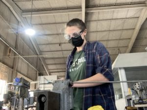
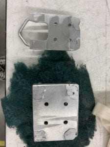
Managed the modeling in SOLIDWORKS of the proposed design along with numerous iterations that followed. Was also responsible for manufacturing of the plates for both components.
Elyse Gillis-Smith
manufacturing & outreach
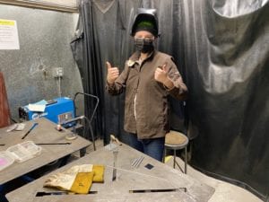
Manufactured and formed metal rods of components. Welded all prototypes and final systems. Outreach ideation and monitoring progress on outreach events.

Michael Roth
testing & budget
Coordinated and performed release force, lunar dust tolerance, and load testing on numerous design iteration. Also managed the team budget and project scheduling.
Acknowledgements
We would like to thank Dr. Peter Schuster and Mr. Gotthard Janson for guiding us through the design process.
Our Project's Video
Our Project's Digital Poster
Project Summary
Our senior project was based around a NASA Micro-g NExT challenge to be tested in the Neutral Buoyancy Laboratory (NBL). The Lunar Surface EVA (Extravehicular Activities) Operations at NASA need a space suit attachment quick release system for lunar missions. NASA astronauts who moon walk for several consecutive hours require a physical system to both secure and quickly release tools from their utility belt. The attachment must be lunar dust tolerant, operable with large gloves, usable without looking at the mechanism, and able to fit the utility belt size constraints.
Design Constraints
- – Support at least 15 lbs of weight in Earth’s gravity.
- – Operable outside of the astronaut’s line of sight.
- – Operable with one hand.
- – Functions after cycled in lunar dust simulant.
- – Install and separate from each other with minimal force, but enough to stay while walking/bending.
- – The device shall use only manual power.
- – The device shall fit within a volume of 4” by 4” by 3”.
- – 4-hole bolt pattern to interface with belt and tool.
– Operable with EVA gloved hands. - – The total weight less than 2 lbs.
- – No holes or openings for entrapment of fingers.
– Only Aluminum 6061, Aluminum 7075, Stainless Steel (any series), or Teflon.
– There shall be no sharp edges on the tool.
– Pinch points should be minimized and labeled.
Concept Selection
After thoroughly defining our problem, we performed functional decomposition which allowed for targeted ideation. Using the ideation results we populated a morphological matrix to combine function level ideas into system level designs. These designs were then added to a weighted decision matrix, shown below.
weighted decision matrix
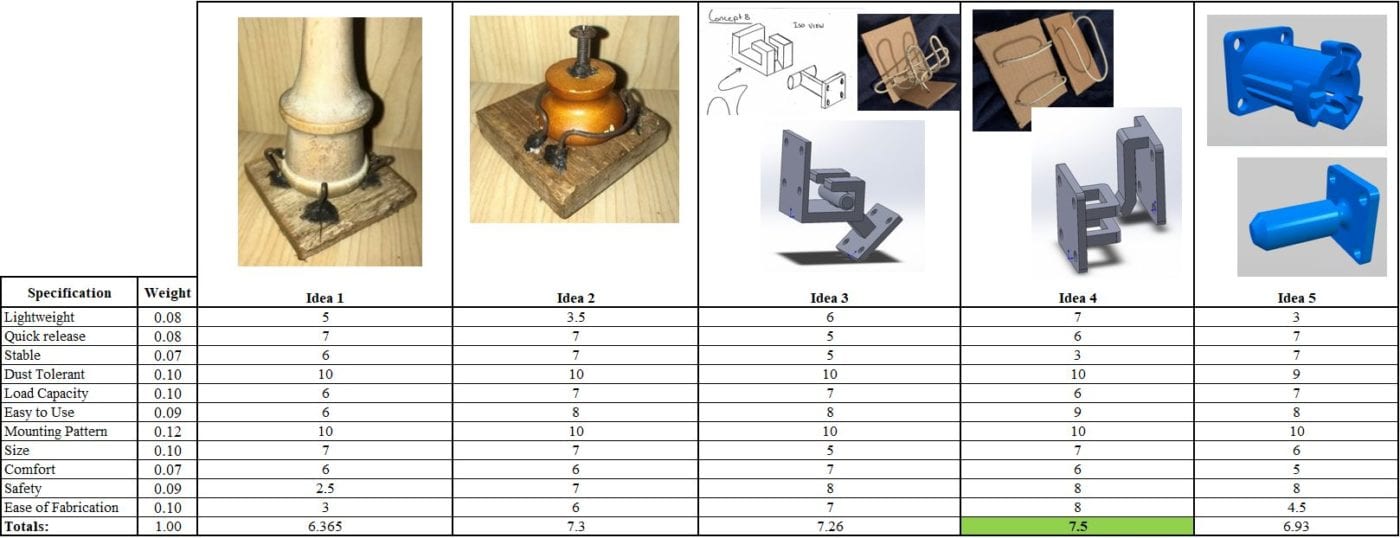
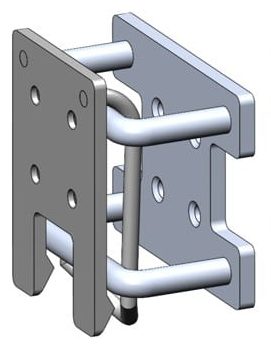
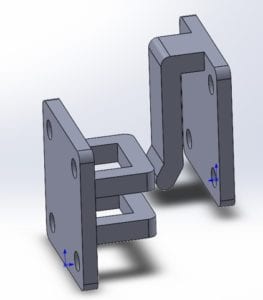
We used a weighted decision matrix to objectively decide which of our top 5 concepts best met our specifications. The design that combined the ideas of a sheath, flexure, and wire frame won and is the concept that we decided to pursue throughout the rest of the design challenge. Below you can see an early concept of our design.
Prototyping
Experimenting with manufacturing through many prototypes provided an immense amount of knowledge and feedback on how to move forward with our design. These prototypes helped with our decision making in rod diameters, plate thickness, material choice, welding techniques, heat treating, and bending rods.
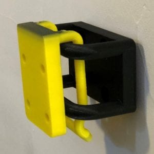
The first prototypes made were 3D printed and allowed us to obtain ergonomics feedback by using gloves and a blindfold to simulate astronaut conditions. Shown below is the very first prototype of our proposed design made with a 3D printer.
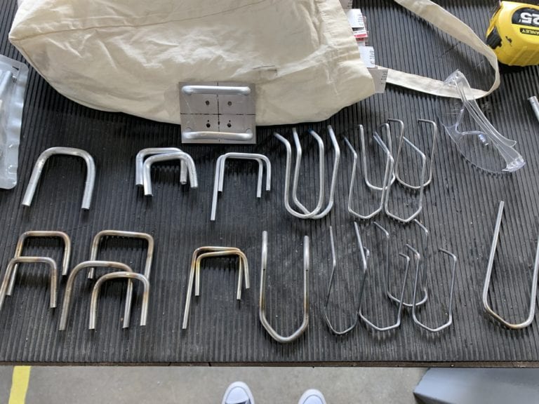
Next we prototyped with Aluminum 6061. This allowed us to obtain a more realistic release force for different probe diameters as well as refine our manufacturing plan. Below is an image of the medley of probes and rungs used to create prototypes.
NASA Micro-g NExT
This project is sponsored by NASA Micro-g NExT Challenges.
Design Progression
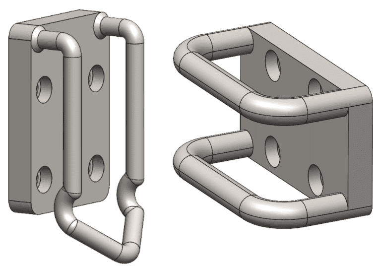
NASA Proposal & Preliminary Design Review Model
Interim Design Review Model
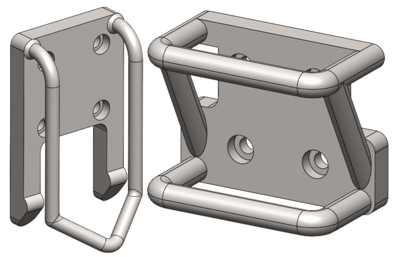
Critical Design Review Model
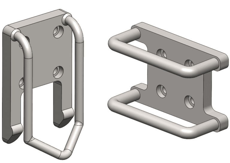
Specification Testing
Main tests
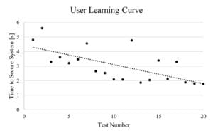
Ergonomics – The ergonomics of our design concept were tested early in the design process to ensure that the astronaut shall be able to easily and quickly secure and release the tool. In this test, Michael Roth wore a blindfold and thick ski gloves to simulate the astronaut’s space suit. We learned that the user quickly learns how to locate the system with all of the physical limitations. The learning curve can be seen below.
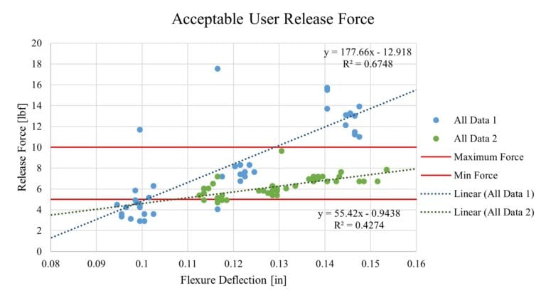
Release Force – Another important specification for our design was that it should be able to release with minimal force for the astronaut but have enough force to stay in place while walking and bending. This test involved securing the system and measuring the release force for various flexure deflections. The minimum bound was determined from an inertial calculation (F=ma) and the maximum bound was determined by astronaut comfort. The release force for given flexure deflections are plotted below. There are two sets of data, one for each prototype.
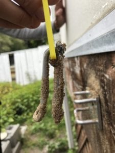
Dust Tolerance – Although we designed our system with dust tolerance as a key factor for consideration, we still needed to confirm that there were no unforeseen complications as a result of dust. To perform this test, we submerged the system in water and then sand to simulate the dust sticking to the system. In the process we proved that our design was in fact self cleaning and lunar dust wouldn’t cause mechanism failure. One unexpected thing we learned was that the sand roughened up the surface of the metal and as a result, increased the release force due to a greater friction coefficient.
Final Design
Specifications
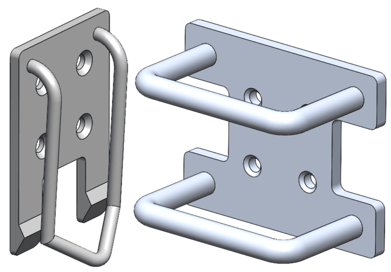
- Volume: 3.25″ x 3.29″ x 1.65 “
- Weight: 0.30 lbf
- Material: Aluminum 6061
- Release Force: ~7.1 lbf
Manufacturing
NBL Testing
Currently, we are awaiting testing at the Neutral Buoyancy Laboratory (NBL). There, our system will be secured to a diver’s simulated space suit and he/she will perform tasks as if on the lunar surface, with ~1/6g and all of the ergonomics limitations. Below are some tests they will perform and things we will ask them to note.
- 1. Submerge the system in the lunar dust simulant and cycle the system. Does it affect its performance? If so, does it make the system easier or harder to secure/release?
- 2. Walk around the simulated lunar surface. Hop around as seen in old videos of astronauts on the moon. Bend over and perform a task. Does the system unexpectedly release?
- 3. Secure and release the system 10 times. How does the release force feel? Is it too difficult, too easy, or just right?

